2023 Update: I have since installed Discover Batteries and a Rego DC-DC charger. I still use the dash switch, but I eliminated the solenoid and IRD.
Many people who have switched to Lithium, particularly with more than 200 AH of capacity, have installed a DC-DC charger.
But I am not quite ready. They steal some of the efficiency, have relatively low output, require a big chunk of mounting real estate near the battery, and its another item to break and ruin your trip.
The Mercedes alternator is rated at 220 amp, but the upfitter guidelines call for a much smaller house charge rate of 40 amps or so. (I have seen as much as 90 amps or even more leaving mine!)
Why such a low recommendation? Well, its an extremely conservative number. But lots of sprinters have heated seats, electric defrost, and all sorts of contraptions running off the alternator, not to mention that it has to recharge the chassis battery between starts.
Untold hordes of folks have dropped in twin Battleborns with the stock alternator, and I am not aware of any reports of melting the Mercedes alternator or blowing the main fuse. Between the long cables which cause voltage drop (and reduced current), and the Mercedes intelligent power management system, it all seems to work out.
Still, it bothers me. When my house batteries are almost discharged and I start the engine I see 90, 100 amps, or even slightly more rushing into my depleted lithium’s. Sometime I immediately get stuck in traffic and the engine is idling which is the most concerning. (Poorer cooling and reduced alternator output)
A switch would seem like a good short term solution. Much of the time I don’t even need any alternator charge – the 600 amps of solar is more than enough. And in almost all cased I’d want to be at cruising speed before engaging warp speed charge.
And lastly I may want to keep the dash switch, even if I later install a DC-DC charger. For one thing at least one of the models on the market does not have any built in time delay, but starts charging as soon as the engine starts, which is obviously sub-optimal. (The factory IRD that I have delays 12 seconds and waits for 13.3 volts before opening the isolator relay).
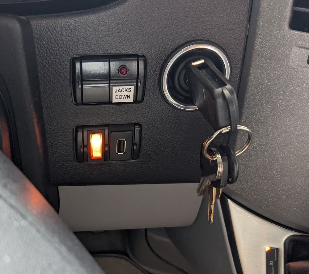
So on to the switch. The simplest would be just to mount it right on the side of the passenger seat, but for a little extra work I used a dash mounted lighted switch. That way its easily accessible, and I can even switch it off for example in major congestion.
I decided to wire the switch after the IRD and on the relay itself. That way if the switch is lit I can actually see that the IRD is working or not.
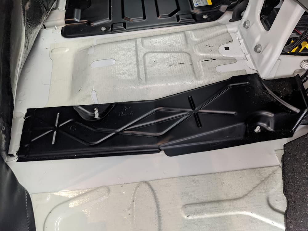
It turns out its all pretty easy. After you remove the carpet there is an “L” shaped trim cap under the doors, and after you remove that, the entire two piece floor mat can be moved. The drivers side I just took off, and the passenger side I rolled back and held up with a piece of Styrofoam by the toolkit.
Next, I removed the large gray curved plastic trim under the center console. This fully reveals the metal bracket that covers the center wiring channel between the seats:
Just remove the 2 nuts to expose the wiring channel.
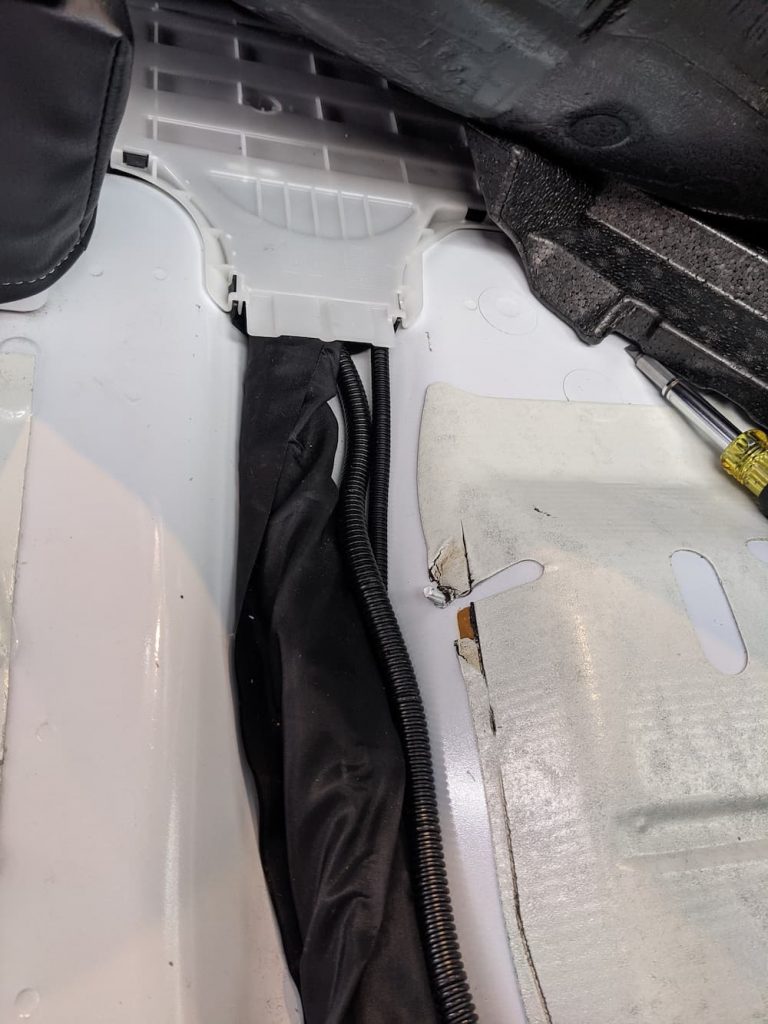
So at this point I just pried up the white plastic bracket behind that, exposing the channel that runs out the side of the passenger seat. Actually I took this picture afterwards, having already pushed the wires through in a piece of plastic wire loom.
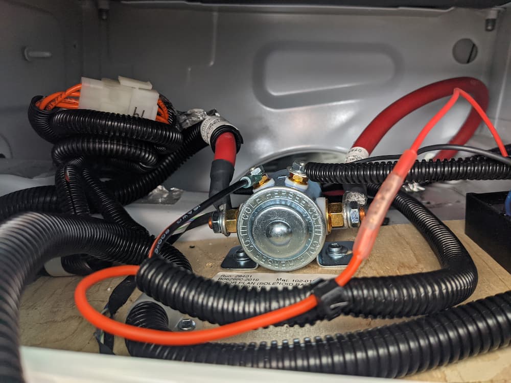
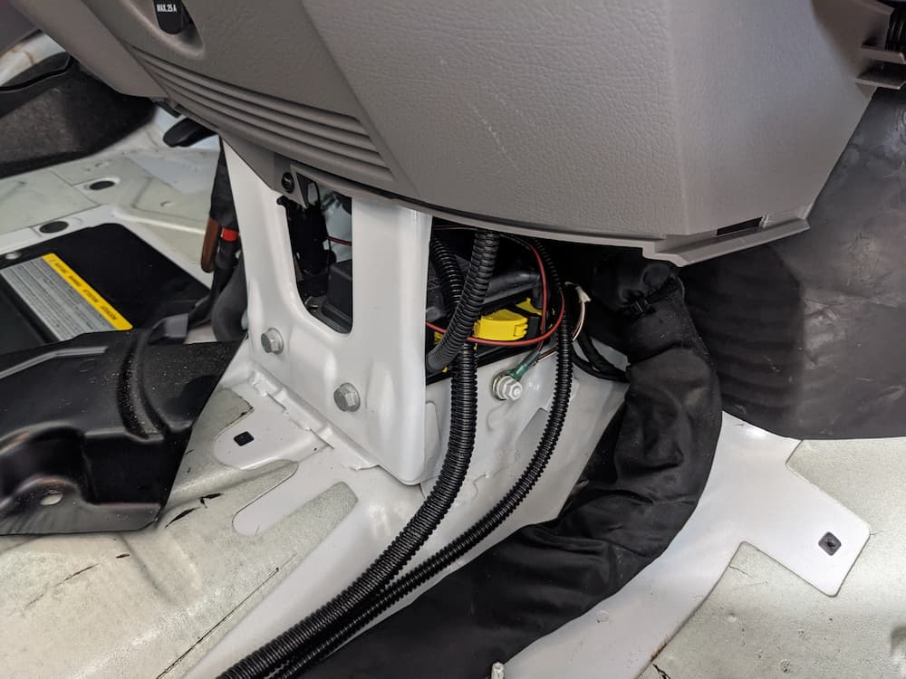
On the outboard side of the passenger seat, you can see the wiring and relay:
So its not necessary to remove the seat or anything else; just the plastic access panel that holds the awning switches.
I simply took the red wire off the relay, and crimped a butt joint to the wire I ran. Note that the red wire from the IRD is quite a small gauge, so I used the smallest red crimp which required trimming some strands off my thicker 16 gauge wire.
Then I simply crimped a small ring on the other wire and mounted it to the relay.
I STRONGLY SUGGEST YOU DO NOT WIRE THIS “HOT” AS I DID. IT WOULD BE REALLY EASY TO CONTACT THE HOUSE BATTERY WIRE ON THE LEFT SIDE WITH A METAL TOOL AND CREATE A FUN LIGHT SHOW!
Because I used a lighted switch, I also need a common wire for the led. Since there is a ground bolt right at the front of the wiring channel thats perfect:
In the picture above you can see the ground bolt.
As an aside, I use the (ridiculously expensive) Ancor crimps for everything. They cost 50 cents to a few dollars each. Compare that with the Chinese crimps on Amazon or in parts stores that sell for a few cents. I have noticed that if I tug on factory crimps in my van its not unusual for the end to come off. With the Ancor crimp, that sucker stays on. It also has a built in heat shrink tube to further protect the connection. I’ll list all the parts below, and the Ancor crimp set, but you can also buy just the ones you need individually on Amazon or in marine stores.
The switch itself I bought on ebay. (Link below) It didn’t come with a wiring diagram so I had to use a meter to figure it out. On my switch it worked out to the brass colored terminal for common, the center terminal is the relay, and the other one is the red hot wire.
After I started the engine for a trial run it occurred to me that the switch may be on the bright side. I’ll have to drive at night to see if its a bother, but I may very well try a small resistor in series to dim it. (It should work on the common side). Obviously I could also pop in a non-led switch as well, but I tend to be on the forgetful side so I like the led reminder.
Here are the parts I used. The switch itself from eBay. The rest I bought off Amazon. I’m also listing useful tools and stuff for this project.
(Links are paid)
Leave a Reply