Dec 2022 Update:
The Renogys worked great after a few kinks were worked out and have been reliable. However I recently upgraded for more power to a pair of Discover Lithium 200 Batteries. The rest of this post is still relevant about installing the Xantrex, busbars, switch, etc. I only later updated the batteries themselves.
Original Post:
This is a big project that involves a lot of stuff, but in a nutshell I bought a Xantrex 3000 XC Pro Inverter/Charger. This is an inverter big enough to run anything in the RV, including my air conditioner (at least for a little while), off of batteries.
There is not much sense to having a giant inverter with only my pair of Battleborns, so I am also upgrading to three Renogy batteries.
First, a huge disclaimer. This project is not for everybody! Unless you thoroughly understand what you are doing (and even then) this project can be deadly. Many of the inverter installs I see online have subtle but serious mistakes. A common one is not understanding that generators and inverters provide a bonded ground point to neutral, whereas shore power must not have such a bond in the RV and assumes that the power supplier has bonded it somewhere – usually the service entrance panel. For this reason you must isolate the neutrals of all your power sources. This is just an example; there are dozens of small errors that may not show up until you get shocked or your rig burns down one night. So this article is just an inspirational guide – not a step-by-step one, as some of the steps I probably forgot to mention!
The reasons I chose these components are pretty simple:
- The Xantrex is compact and lightweight, and has just enough features for me. (The well known Victron is heavy and the form factor is all wrong for the space I have).
- My current 200 AH batteries are just barely adequate, and probably lack the punch to run the AC effectively for any time period.
- Three batteries will yield 300 AH. Thats probably a sweet spot for years to come. Much more and you aren’t going to be able to recharge daily with solar anyway.
Note that I sort of did this “the hard way”. It would have been a WHOLE lot easier to install a single Lithionics 320 Battery. However that would cost 2-3 times as much and be a single point of failure. (There are lots of single points of failure in RVs, but having a single house battery just seemed a bridge too far to me.)
If the Lithionics were to fail thousands of miles from home you just can’t stop in an auto store and pick up a replacement. You would have to ship the $4,000+ thing to Lithionics in Florida and wait for turnaround however long that is. (I can’t even drive my RV safely without a house battery because of the Equalizer jacks.)
So having 3 batteries, while a lot of work, seemed the better choice for me. I can afford to have one fail (or in a pinch, even two, and proceed on my trip.
The other great analogy is that in the 80’s when I was designing large computer systems, we were putting in larger and larger (and more expensive) disk drives for storage, and guess what? When they failed, it was really devastating and expensive. Then some geniuses at the University of California at Berkeley in 1987 came up with a new philosophy they called RAID (Redundant Arrays of Inexpensive Disks).
The idea was, just wire together cheap commodity disks in arrays and plan for occasional failures that no longer disrupt operations and are cheap to repair. In fact don’t even repair – when they fail, just throw ’em out and replace.
Google later took this philosophy to the moon to scale to almost unimaginable size.
So I am thinking thats a good strategy with batteries too. I can install these now, and if in a couple years even denser and cheaper and more useful batteries come on the market, drop in some new replacements, and still have spent less than if I invest in a single large battery today.
The Renogy is also a bit on the larger size for a Group 31 Battery. That means that I will be able to drop in replacements when the time comes from a variety of vendors.
For me, the 5 and 10 year warranties offered by “Top Tier” vendors are not that compelling. Realistically I’ll probably be upgrading these in 2-3 years as better technologies emerge, which is why I am not really counting On Renogy’s (well earned) poor performance when it comes to warranty and repairs.
Why Renogy? Well, a key requirement for me was the Bluetooth. This technology is a game-changer for knowing whats going on inside each battery right down to the cell. I didn’t want to buy any more batteries without Bluetooth, which ruled out simply buying another Battleborn – which is already obsolete in my view.
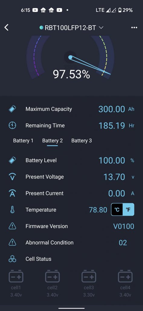
For reference here is what that app looks like when everything is wired up. As you can see you get a lot of the information that a battery monitor presents, including remaining time and SOC.
But you also get information for each battery, including right down to the individual cells:
So my requirement for Bluetooth left an expensive field of just a few players – Lithionics, Volthium, Victron, and LifeBlue to name some.
The Renogy was unique for being absurdly cheap – just $479 on eBay. Will Prowse did a teardown of their previous battery and blessed it, and Renogy generally makes good products albeit with terrible/non-existent support. Apparently they have not been able to get much traction with these because people are comparing them with the even cheaper batteries you can find on Amazon or Alibaba.
But I’m placing the Renogy batteries in more of a top tier category based on what I can see – without actually sawing one open.
Renogy has this slick video of the battery internals. Not sure how accurate it is but I like the heavy top bus bars and bms on the side. Look Ma – No wires!
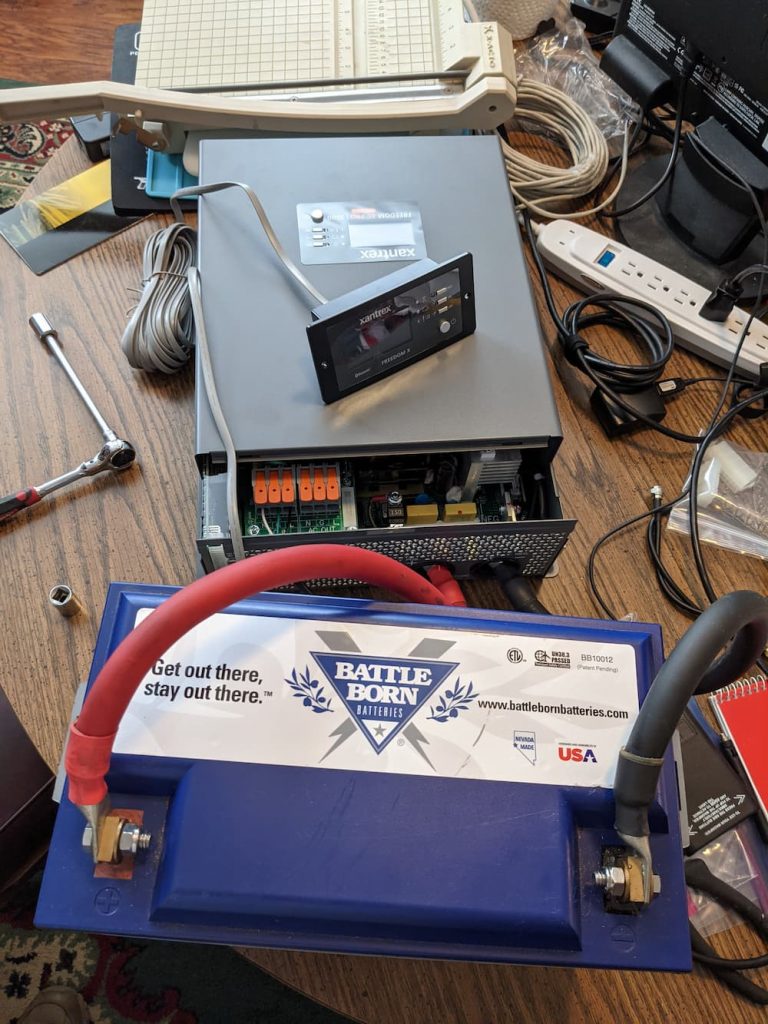
The Xantrex showed up first so I put it on my messy work table to test. The first thing I did was connect an AC cable and boot it. It seemed to work, so I connected the remote panel. After updating the firmware I was able to use the Bluetooth app instead of the (horrible) panel(s). Then I derated the charger down to 10 amps. (Its 150 amp capacity is both too much for one battery and also enough to maybe blow the 15 amp breaker).
Then I turned it off and connected one of my old Battelborn batteries and everything seemed to work fine. I didn’t connect a breaker on the DC side for this short test but you should!
Note that its not a good idea to connect a single small battery like this to a 3000 watt inverter. There are large capacitors inside and the initial charge may trigger a bms turn off or even fry the battery! But I did it anyway and I can report that nothing fried or turned off.
Its really an amazing tribute to Battleborn that just a single one of their batteries can charge a 3000 watt inverter, something way beyond its specifications! I should mention I also tried the same experiment with a single Renogy battery – and – likewise no faults or damage.
I like most things about the Xantrex. Its simple and lightweight. One thing I didn’t like which is a complete joke is the 20 pin communication harness. I wanted this so I can install a remote switch. Its sold online for around $120. It looks suspiciously to me like a standard 20 pin Molex connector ($1.05) on Mouser, and in fact I verified it is. You can buy a wildly overpriced kit on Amazon which includes the connector and a bag of pins for around 8$.
Xantrex should have just included the $2 (wholesale cost) harness in the box instead of trying to pimp them out for $120 in my view.
I later decided to mount the Bluetooth panel inside the RV. The panel has a soft on/off switch, so it turned out I didn’t need the Molex connector anyway.
So on to the install!
At first, it seemed pretty overwhelming.
The way I look at these things sometimes is – just start over. What I mean, is one time I had a badly mis-wired home gang switchbox. It was huge – like 8 switches or something, and hopelessly mangled with more than one hot wire and bad wiring. Studying the mess was overwhelming and confusing, and I couldn’t really see exactly what was wrong.
The solution was to rip everything out, discarding all the wiring and pigtails in the box, and then label everything (either by guessing from its original wire, or later, by toning out the wire to see where it went).
Once the box was empty and nicely labeled it was trivial to correctly wire everything up.
So I’ll be following the same plan here without much regard as to how everything was wired beforehand!
You have to start somewhere, and I decided on the WFCO panel:
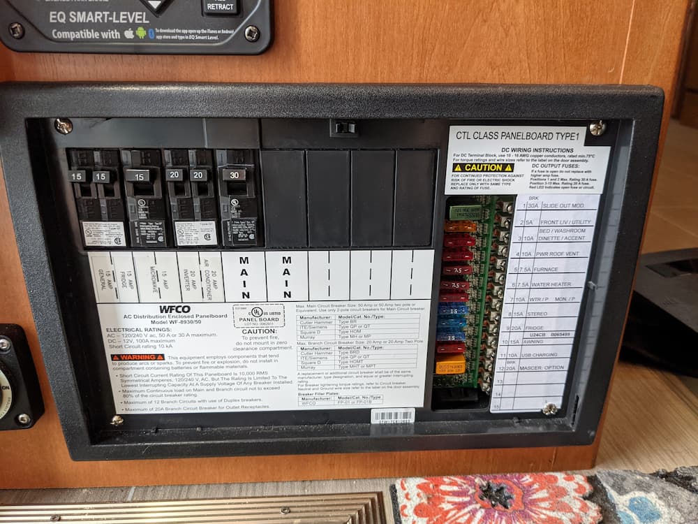
This thing has always been just a mystery box to me, since I have never opened it. So lets see:
So it turns out its sorta just like a home service panel, only they also stuffed in a 12 volt fuse panel on the right. Lets ignore that part for now.
Otherwise, you have a 30 amp main breaker and 5 service breakers. The way the RV is wired is, the main goes to the big transfer switch up front that switches between generator and shore power. On my RV its under the bed.
The right side is a whole other unused bus, so the box can also be used for 220/240. Neat, because thats exactly what we need – a separate bus. Once side for shore power, and one side for inverter power.
My current inverter is a separate deal. Its output goes to a couple outlets only so you can run the TV and recharge your toothbrush but not a whole lot more.
So what we want to do is, simplify all this. The new wiring will send everything through the Xantrex, where its internal transfer switch will flip between live current and inverted current. In either case the output of the Xantrex will now be wired to the main you see above.
Then I’ll locate the current inverted circuits and add a new breaker for them on the WFCO.
So the new current flow is main transfer switch under bed –> Main Shore Power breaker on right bus –> Xantrex Inverter –> Inverted Main Breaker on Left Bus -> Rest of Coach.
(I’d rather my compressor fridge not switch to AC unless its real AC (generator or shore power). It doesn’t really matter, but if my fridge uses even one amp on inverted AC its taking away from the available 25 amps, albeit just a bit.)
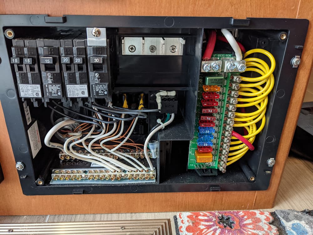
So it turns out you can use the WFCO as (2) 120 Volt panels by simply splitting the neutral bar in two. One half for the side connected to shore power, the Xantrex, and the Fridge. And the other side for everything else.
So I put some new breakers and labels in. The breakers are standard breakers. What is going on here is, the new right side “Main” is the “Shore” connection.
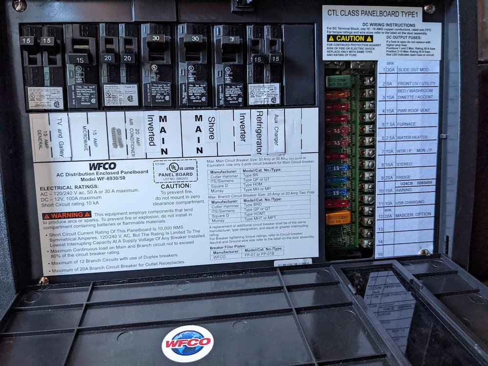
That right bus will power the inverter and refrigerator. The output of the inverter goes back to the left main (and everything else). I also installed a small Victron charger labeled “Aux Charger” on the right side. This is wired to the built in outlet on the WFCO. I will always keep that breaker off unless the Xantrex fails while traveling.
Note: Technically this is not a supported configuration for this panel, because only a 20 amp sub-panel is recommended, and many have installed a separate external 30 amp breaker. But after reading the documentation carefully, I determined for my usage that there is no reason for a separate breaker for my RV. Each bus (left and right) is rated for 50 amps, and using one side as a 25 amps sub-panel for the other, while not supported or tested, is well within the safe operating range in my opinion. But if you want to stay within manufacturer guidelines, you should use an external 30 amps breaker. And you probably should not be taking any advice from some random internet poster (like me) and do your own research!
The first step if to remove the neutral bus and saw it in half, leaving about a 1/4″ gap. This is critical because the 2 sides of the box will now come from separate power sources. This picture was before I added the “Aux Charger”.
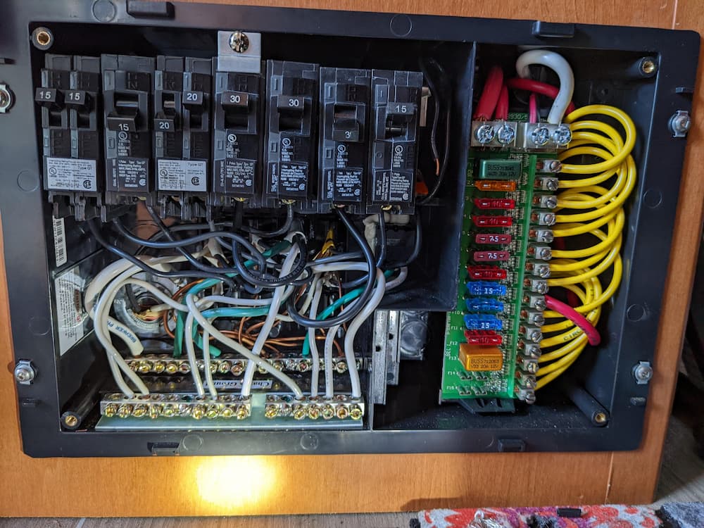
If you look at this picture you can see the right side (shore power) neutral bus is now isolated from the left side (inverted) neutral bus. There is only one ground though. This is an acceptable configuration.
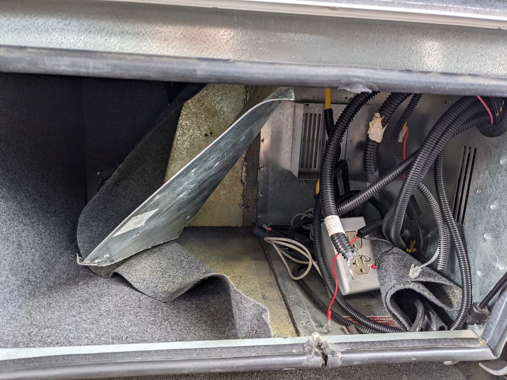
The area under the sink is where a lot of wires are located. I popped out the drawers to see what is going on. The left side is the rear of the WFCO. I assume one of the dummy AC outlets is tied to the mains and one is inverted – guess I’ll figure that out later. LTV is just using these as junction boxes I assume.
The opened box in the middle of the pic is my Old Equalizer Stabilizers controller. Since thats no longer used (I installed their jacks instead in 2021) I started by removing that box. One cool thing is that now I have a whole bunch of wires I can re-purpose later, as some go to the equalizer switch above the entry door an some go underneath to where the motors use to live. I have a whole bunch of plans for these wires – more to come on that subject!
One complexity I have is that we may need to use our RV for some short trips soon, and I am reluctant to just start ripping things out. From past experience I know you can get stuck weeks waiting for some obscure part, especially these days. And I frequently redesign partway through projects.
So I’m going to start ripping stuff out, but leave “just enough” stuff laying around so that I can quickly throw the RV back together if necessary.
To that end, I started by removing the batteries. I immediately discovered I can’t even drive the RV that way! My Equalizer leveling jacks beep continuously when I start the engine with no coach battery.
So I temporarily put back a single lonely Battleborn.
This will give me just enough battery to go on short camping trips (as long as I have hookups), yet can be removed in seconds to continue working.
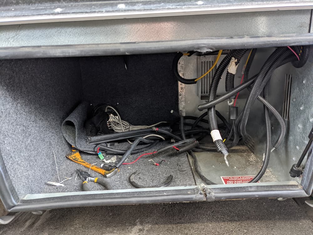
Next, I removed my lithium battery charger and Magnum inverter, and a lot of associated wiring. This frees up most of the compartment. To be able to keep the RV plugged in and with security cameras and internet going, I purchased a Victron 25 amp lithium battery charger. This little charger can be hooked up temporarily during my project.
Its such a nice little charger that I plan to keep it in the RV for backup.
So here is the before picture:
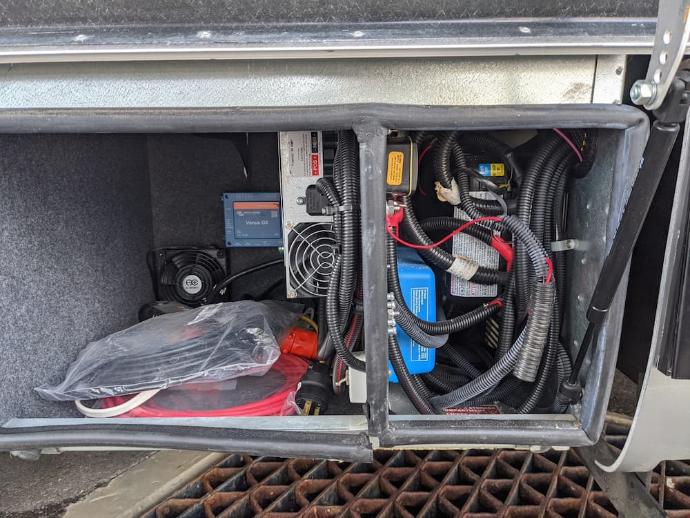
The right side has the Magnum inverter installed. I added the Victron 50 Amp MPPT Solar Charger. As you can see it barely fits, and resulted in a rats nest of wiring. On the left side is the Progressive Dynamics Lithium Charger and Victron Venus. All that stuff worked great, but the right side is crammed into such a small area that access is brutal.
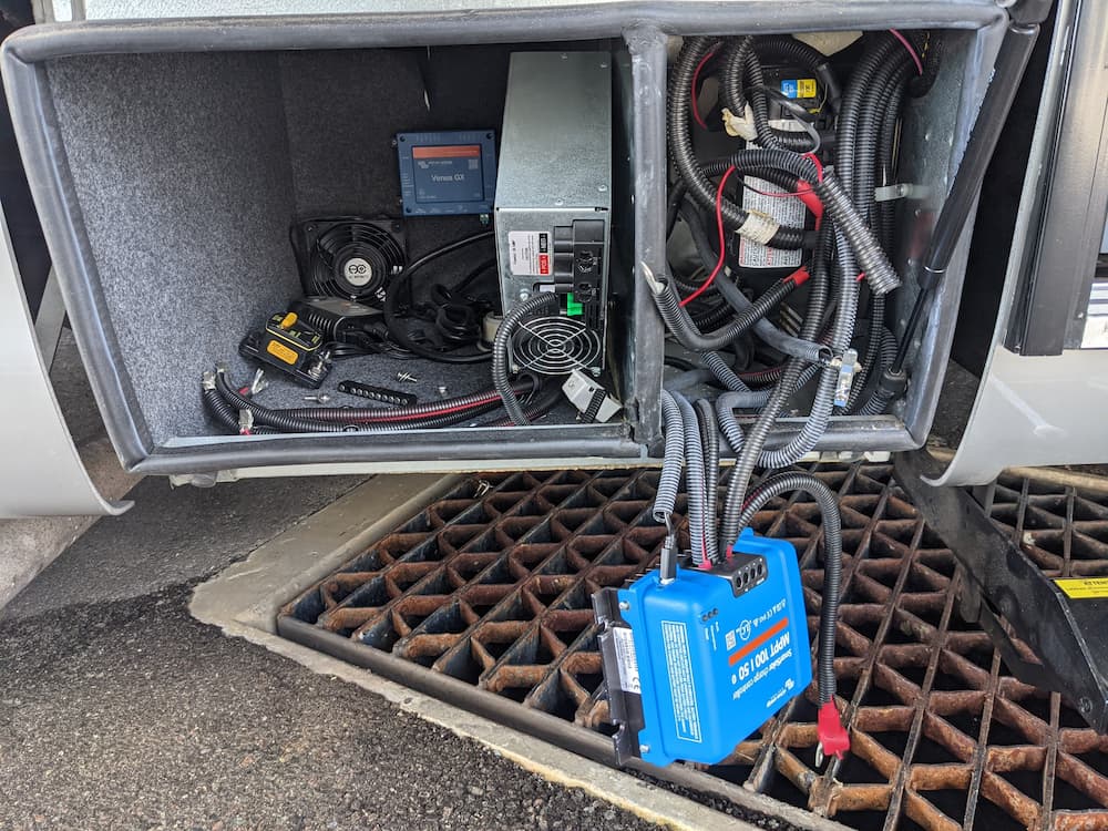
I started with dropping the lithium and solar chargers:
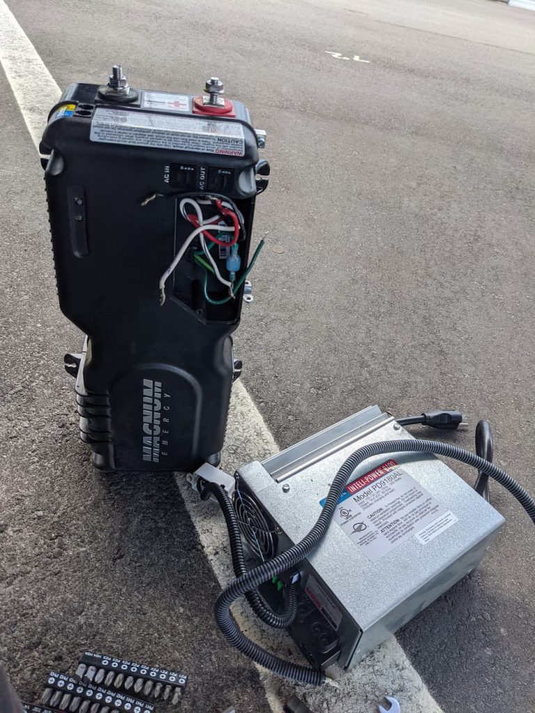
Tearing out the Magnum was especially brutal as I had to reach in up to my armpit to get at the small screws. It probably took an extra hour just to get the last 2:
Victory! With those suckers on the ground I was done for the day so I wired up the temporary Victron charger:
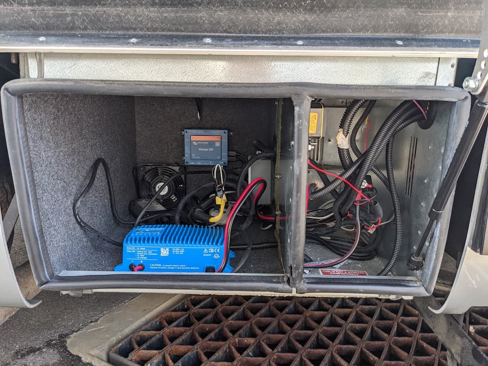
I store my RV in a public storage lot, so I like to leave it plugged in. That way I have security cameras, chassis battery maintainer, etc. Wiring the Victron backup charger only took a minute and allows me full RV operations. In fact we could actually go camping (and did!) as long as hookups were available (no solar OR inverter installed).
I opened the front of the WFCO service panel and traced the refrigerator cable. From the back I clipped off the cable. (The WFCO uses a plastic strain relief that is devilishly hard to reverse, so since there is plenty of cable it was easier just to cut it.)
I labeled it “Fridge” even though its not likely I’ll forget where it goes. (I removed this wire because later I want to connect it to the un-inverted power.)
The (now empty) fridge breaker was 15 amps, so the next step was to pull the old 15 amp “inverter output” out. That is going down to where the magnum used to be, and easily pulls out through the floor.
This line on my van was the inverter output circuit which powered a few things on the side of the RV including the TVs and galley outlet. They were all dead since I disconnected the Magnum inverter. Having pulled it up through the floor I just stripped it back.
Then, I just pushed it into the service panel where the fridge used to be and connected it to the (newly) unused breaker there. So Refrigerator on the service panel just becomes Galley/TVs and now the service panel is complete except for rewiring the mains and fridge. After turning the coach back on all AC now works as expected.
Back outside, the next step was to remove the separation wall so I can have one big compartment. I did it the brutal way – with a dremel and cutoff wheel. Later, I realized that the tiny notch left behind interfered with things, and I discovered a cold chisel and a hammer worked pretty good to remove the rest, so I might just as well have saved the work and done most of it that way in the beginning… The dremel with cutoff wheel was useful on the couple screws that held the inverter air gate though.
The carpet came off easily but left a horrible glue residue; more on that shortly.
As a sanity test I once again test fitted the inverter. I’ll be placing it on the left as I want the right side for batteries to be adjacent to the single battery I’ll place in the step – so all the cables can be the same length.
On to wiring stuff up!
I’m short on space and like things neat so I went with Marinco Pro Installer for a Class T fuse, switch, and busbars.
I went with a battery bus bar for many reasons, instead of the usual “diagonals” method:
- It is kinder to the batteries, since each battery has exactly the same amount of cable
- I can use smaller 2/0 cable to each battery, saving the 4/0 for the aggregate
- I can fuse each battery separately
- It is easy to drop a battery out of service if it fails on the road
This is what it looked like on my desk fitted together:
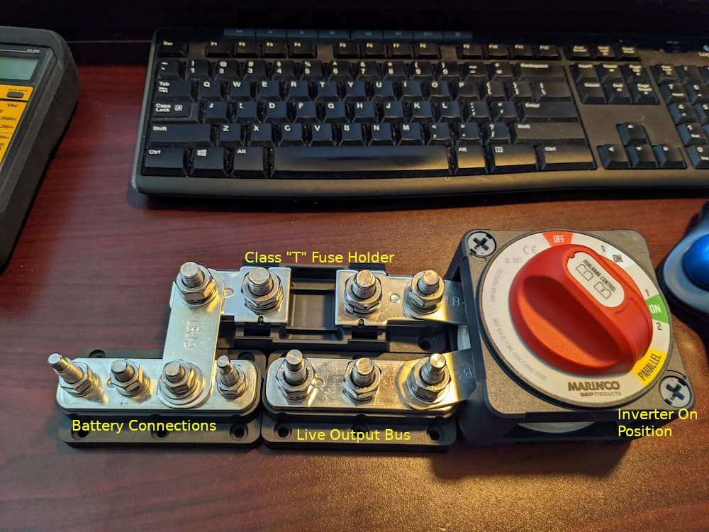
The beauty of these products is that you use their link bars in various sizes to put everything together. So at the lower left I have my battery connections. Then a link bar gies up to the Class T fuse holder. Then another link bar into the switch, and a link bar out of the switch the the “live” bus.
In addition to all this, the “Parallel” switch setting will turn on the Inverter, which is connected to the switch right there.
Here it is mounted:
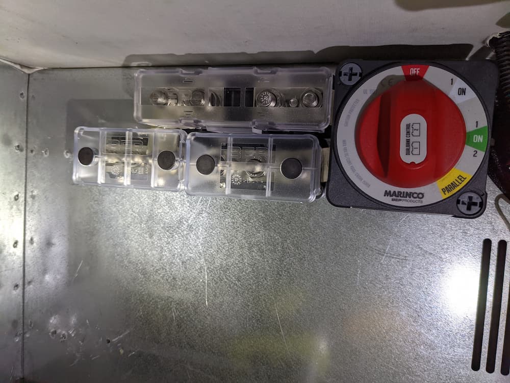
With the dust covers snapped in place, this is a really elegant way to partially corral a lot of wiring. More efficient too, as link bars have a very low resistance.
For negatives, I used a Blue Sea Bus Bar and a Blue Sea Link Bar that connects the battery shunt for the Victron Battery Monitor. I used the Blue Sea instead of Marinco here simply because it happens to have similar height to the Victron shunt so the link bar fits flush.
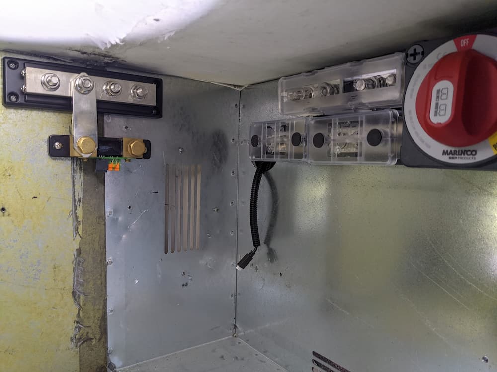
You can just see to the left of the Marinco stuff that I first drilled a large hole so I could easily pass cables to the step compartment.
So here is the setup: (I later reversed the battery shunt for easier hookup)
Its nearly 100% impossible to remove the yellow glue that remains when you rip off the carpet. After trying heat guns and chemicals I gave up. Instead I purchased aluminum sheets and just covered it up. Unfortunately some idiot had already mounted the negative bus bar, so we will patch that little piece later rather than remove it. The overall effect was pretty nice and it will be mostly all covered later anyway:
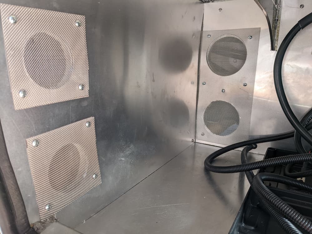
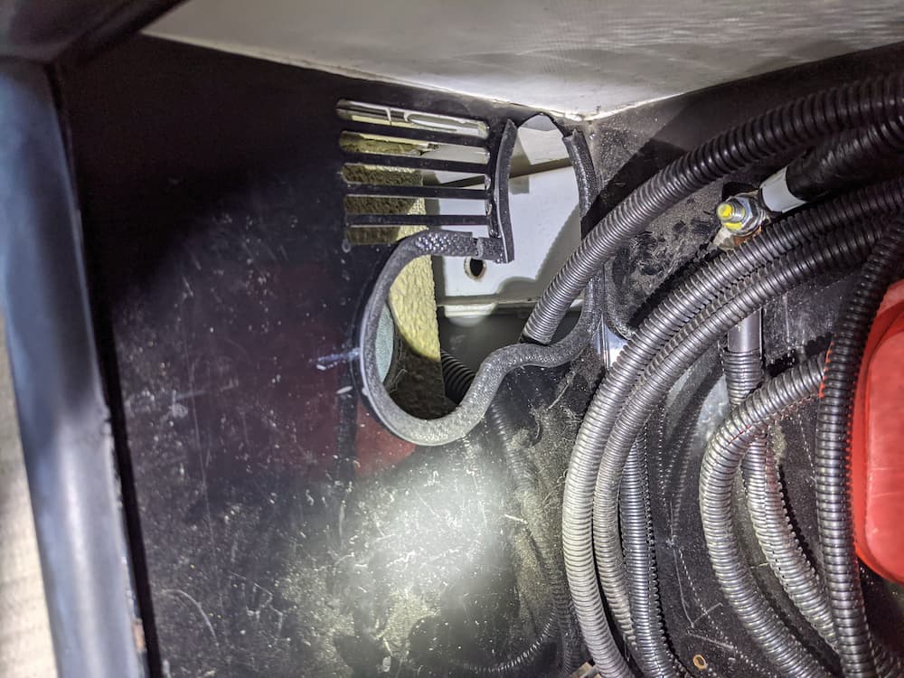
Next I cut some ventilation holes. The rear fans are about where the holes are cut – thats the intake – and the smaller holes in the front for exhaust. I am on the fence about installing water diverters outside or a fan – we’ll see about that! I covered them with a stainless steel screen material.
I placed 2 square aluminum box tubes (using VHB tape). I also covered them with 1/8″ thick rubber on top (using spray adhesive) so my inverter will have a smooth ride and dropped the inverter in. Under the chassis I located the original ground wire for my old inverter and the 6 ga. was adequate so I drilled a hole in the back just right of the inverter and routed the original ground cable:
The inverter is only held in place with a single screw on the upper left – the only one I can easily reach. And since I want it to be easy to remove, I installed a piece of aluminum angle to hold it on on the back right. (I also covered the side of the angle with 1/8″ rubber). The result is that the inverter is extremely secure – yet easily removable.
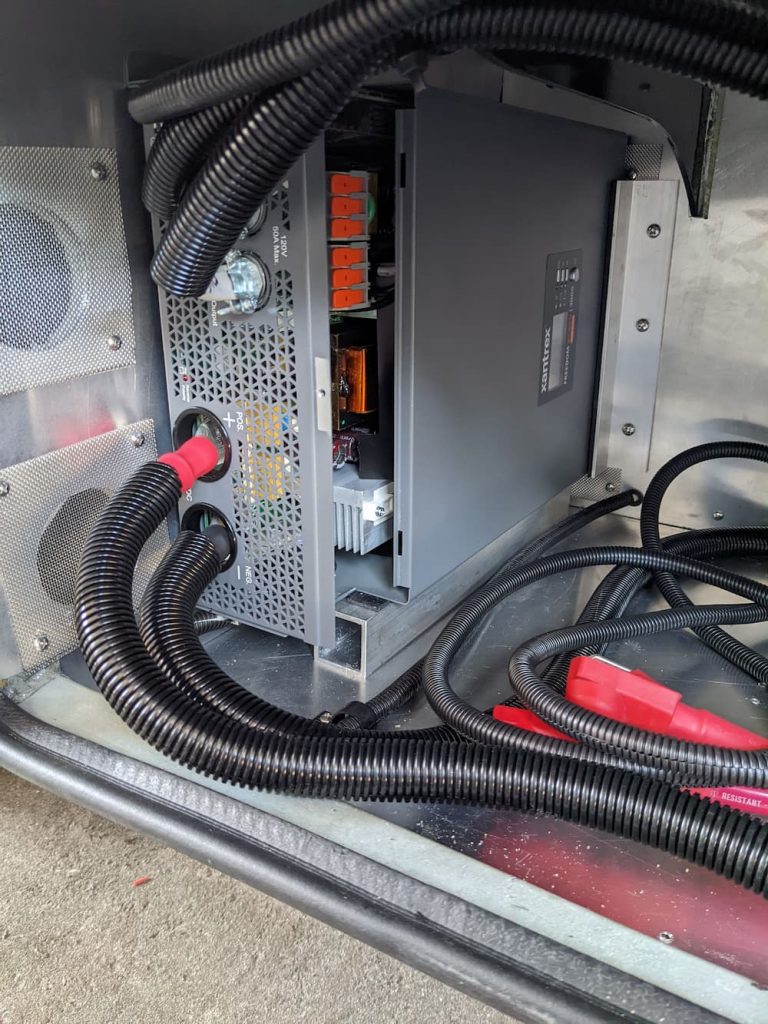
I used ANCOR marine 10 gauge for the AC cable because I felt its stranded tinned copper would work better in the WAGO style connectors the Xantrex uses. Be sure to tin the ends with solder as Xantrex recommends.
The 4/0 cables from the inverter were next – the positive directly to the Marinco switch – and the negative joins directly to the Victron Battery Monitor shunt.
I also made a divider section. While I feel its safe to mount the inverter next to the batteries without it, these things produce a lot of heat. In hot weather I don’t want the inverter to work as a battery heater, so I made this part:
This will isolate the inverter (I’ll put in a little HVAC foam around the wires that pass through. So here is what it looks like mounted, using small aluminum angle stock.
Next I finished crimping a ton of wire! I’ve experimented with different crimpers before and this time I bought a TEMco hydraulic crimper which makes these beautiful crimps:
I also bought their massive 500 MCM Wire and Cable Cutter which cuts this stuff like butter.
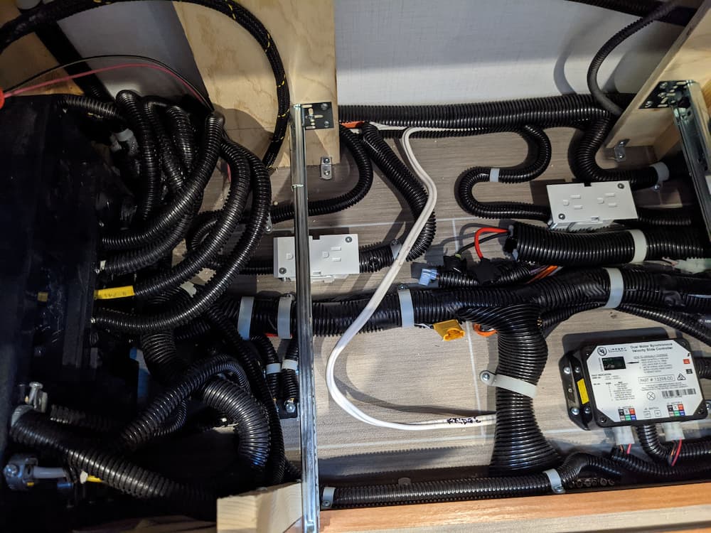
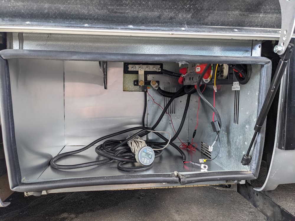
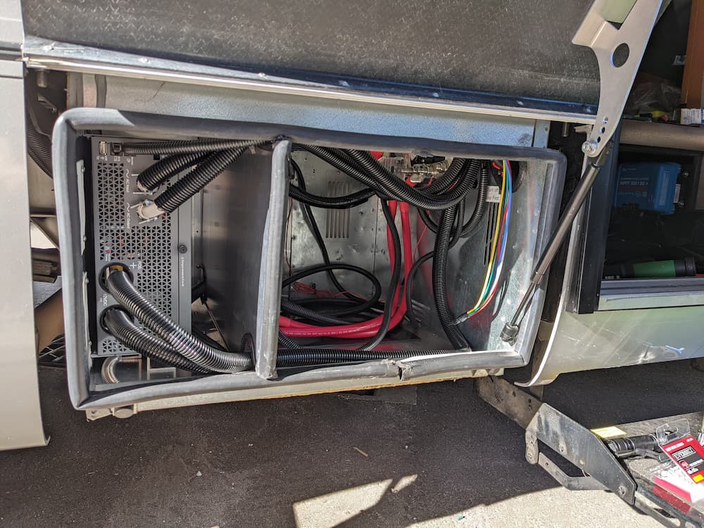
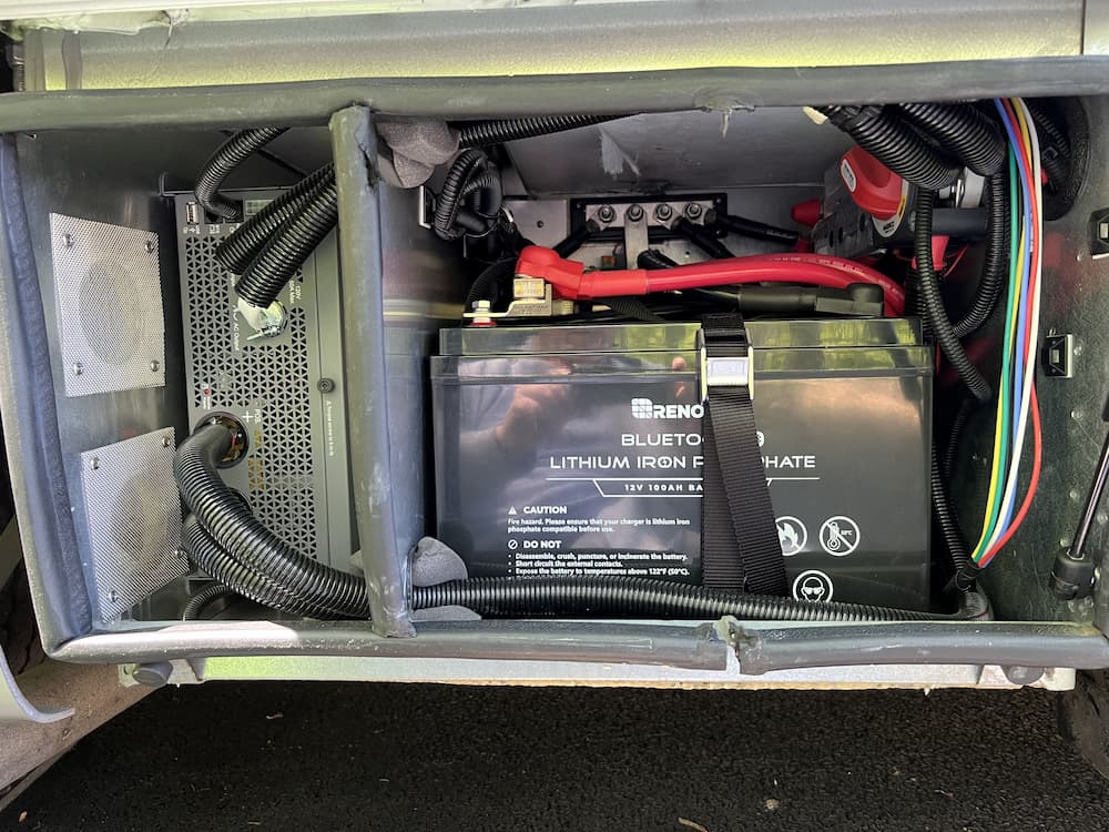
So then it was just a whole lot of wiring and figuring out how to stuff everything in. Here is a picture of the completed bay, which includes the inverter and (2) batteries. (The third battery I installed under the step.)
I used Blue Sea Terminal mount fuses. The big Class T 350 protects the 4/0 cable. The individual battery fuses protect against a dead short across one of the batteries.
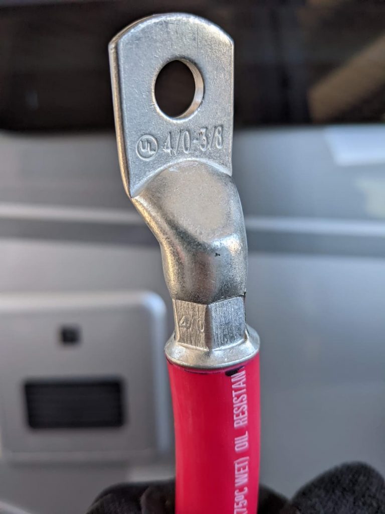
Each battery is wired using the smaller 2/0 cable. I used ANCOR marine wire and lugs. This is one tough cable but its still easy enough to bend. You definitely want to be extra picky about the wire and lugs in my opinion.
(The aggregate cables, and cables to the inverter, all use 4/0 wire)
You can barely see it in this picture, but the big Marinco switch is still easily accessible on the upper right.
Note the colored wires hanging down on the right: I was able to pull both 10 gauge ANCOR AC cables through the old hole in the floor without any drilling. There was also room for this wire bundle. So in the future if I want to add a cabin propane switch or other upgrades I already have a path from here to under the drawers.
Back under the step, I installed a single battery. First I enlarged the existing hole so I could stuff a lot of cables through:
As you can just see in the picture there is a corresponding hole I drilled in the adjacent compartment. Wired this way, the third battery under the step is about the same distance from the bus bars as the other two, so all the cables are the same size in keeping with best practices.
Also, on the upper wall you can see the original LTV ground bolt. This is where LTV wired the battery negative and some other negatives. I decided to simply reuse this bolt, so I later slipped my 4/0 main negative on the the bottom of the bolt.
The completed step compartment looks like this. It would have been too tight with the terminal mount fuse so for this battery I put the fuse on the other end of the wire – at the bus bar:
As you can see, everything is now easily accessible. There are 2 breakers on the rear wall. One is for the Equalizer jacks. They need a breaker instead of a fuse because occasionally the Equalizer panel crashes and needs a reboot.
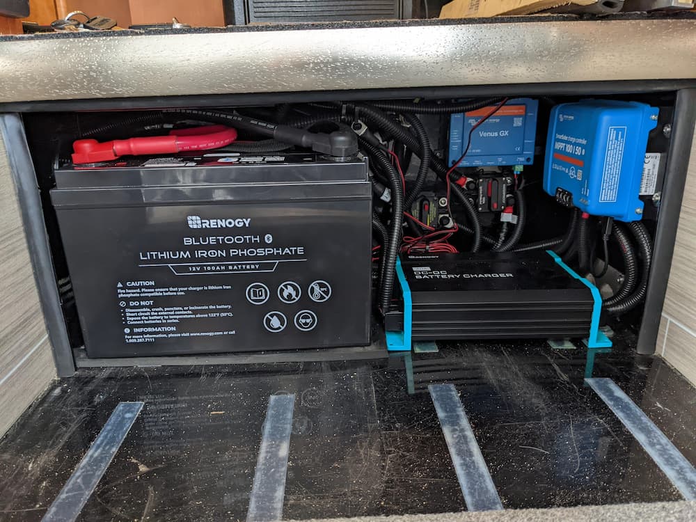
The other breaker is for the input of the Renogy DC-DC 40 amp charger. It needs its own breaker or fuse holder on the input as the other side has a huge fuse and wiring.
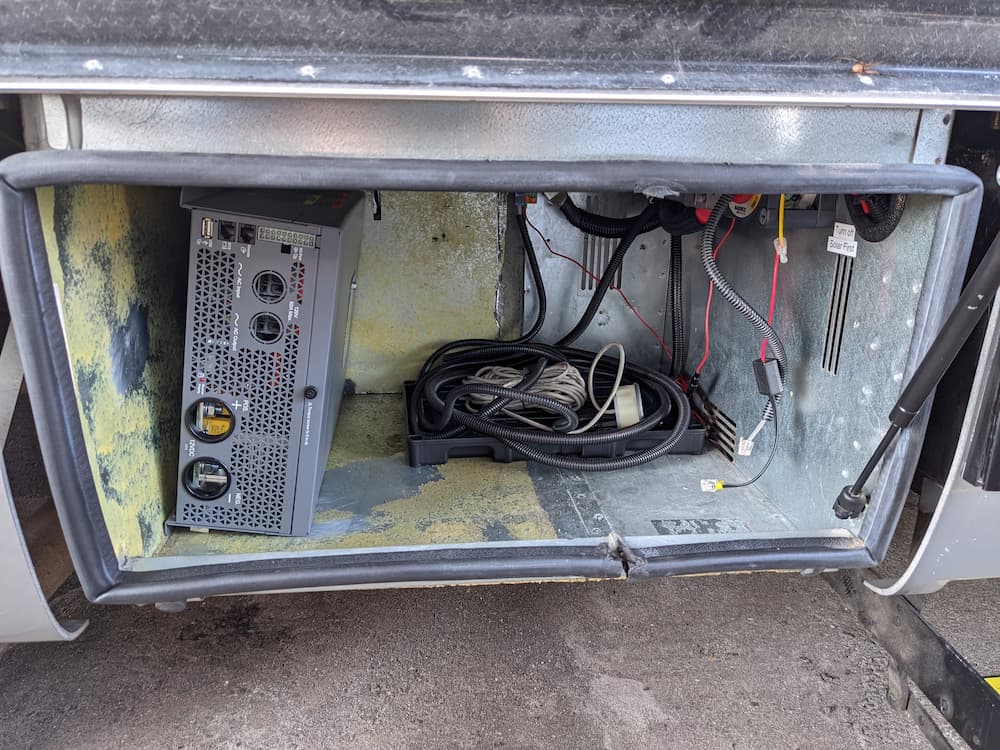
On the right I mounted the DC-DC charger, the solar charger, and the Victron Venus. The DC-DC charger has exhaust fans on the right side so there are 2 holes I added for ventilation and also covered with stainless steel screening.
Someday I will get around to wiring a dash switch for the Renogy. For right now, I already have a dash switch as I left the under-seat Solenoid and IRD as is. When I get around to someday pulling the passenger seat I will remove the (now obsolete) solenoid and IRD, and extend the switch from the battery bay instead.
I used 90 degree lugs on the left side of the DC-DC charger so it would be a good fit.
I added 60 amp fuses to the existing Busman mega fuse holder. One for the solar output and the other for the DC-DC charger output. Neither will ever fail unless there is a short, and it made for a neater and more compact wiring job.
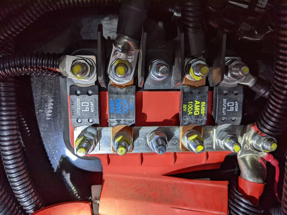
The factory Bussman mega fuse holder is rated 300 amps continuous, and was already installed and is perfectly adequate. On the bottom right is the big 4/0 wire from the battery bank (remember, its already protected by an on/off switch and a 350 amp Class T fuse in the other compartment. Conveniently, I connected the coach jacks on top of it.
The factory 100 amp coach fuse and the 200 amp generator cranking fuse were left as is – the other original fuses were no longer needed and removed.
Back inside, I mounted the Victron battery monitor and Xantrex display by the entrance. I was never a big fan of mounting stuff here, but Equalizer Systems had already mounted the jack controls. I rarely look at any of them (all are easier to use via Bluetooth), so I just took this easy solution. Note that the switch on the Xantrex is used to power on the Inverter function – so its easily reachable there without going outside to actually turn it off.
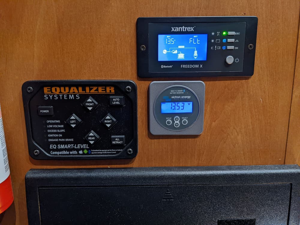
The slightly off spacing is because I plan to later install additional switches and controls under and to the right of the Victron monitor. Edit: I lied; its because when I cut the hole for the Xantrex I forgot to count the width of the bezel.
When I eventually powered everything up together, it all works great! (Its very important to charge individual batteries first to a similar voltage before combining)
The Marinco switch encourages you to first turn the batteries on with one click to the right. That way if they are sleeping (Renogy batteries turn themselves off after 24 hours of no activity) they “wake up”. Then if desired you can click down to the last position which joins the inverter.
(The inverter has big capacitors which can turn off or even fry some lithium batteries, so its a good practice to be sure all the batteries are awake and in good shape before turning on the inverter.)
Immediately, I had some problems with the #1 Battery, which pretty consistently threw “cell over voltage” errors when fully charged, and then turned itself off and stayed off. Thats not great, because if you didn’t notice, its voltage could fall way below the others over time.
These sorts of errors are perfectly normal for new batteries, but the bms seemed decidedly quirky to me.
After some experimentation my solution was to lower the absorption voltage to 13.7. So you still charge at 14.4 volts but after the bulk charging completes the absorption phase stops when the batteries reach 13.7. This seems to work repeatedly well enough for now, and perhaps the batteries will balance better over time. In any case this strategy still maintains the batteries at over 98% SOC so its no big loss.
Overall, I am very pleased with the performance. I still need to do some more testing but everything works as expected. The Renogy app, which I originally dismissed as buggy, is actually perfect once you understand its’ quirks. For example when you launch it, it makes a single Bluetooth connection one at a time. If you don’t wait for 3 blinks it will be missing some batteries.
I still have to install the AC soft start kit to test. But using 2 space heaters and pulling 2000 to 2800 watts, everything just purred along. I’ll update as I complete the AC work.
Feb 2022 Update:
I finally got around to installing the Micro-Air EasyStart for my Dometic Penguin II AC.
The EasyStart is a soft start device that will let the AC start using less peak amps, potentially letting the AC run longer off of batteries, or, when plugged in to sketchy electric, possibly even a 15 amp outlet.
It was relatively easy to install. The best video I found online was at Micro-Air Install. Those instructions were nearly perfect, but they failed to mention what to do for heat pumps. Using the instructions provided by Micro-Air I simply removed the purple wire from the old start cap and added that to the common of the run capacitor. Also for my unit I had to mount the box on the other side of the AC following the path of the compressor wiring.
Be sure to use the Hutch Mountain kits with the Bluetooth and Wago connectors, link below.
This new version has a cool Bluetooth interface so you can see what is going on.
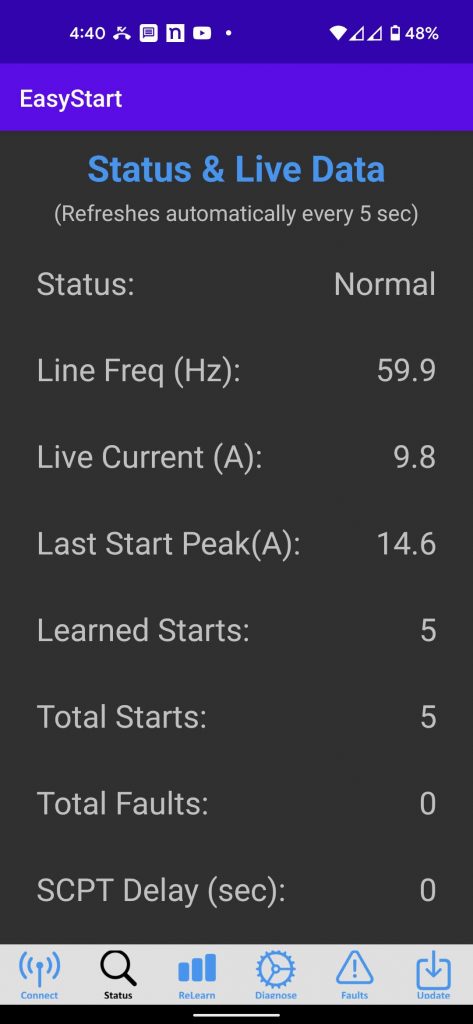
This really was a thrill of victory – watching the AC start and run off of batteries. The Renogy batteries reported about 150 amps running and a projected life of 2 hours. But that assumes the compressor runs full time; obviously that assumes the AC never cycles, so more realistically I think I could expect at least 3 hours or more of AC even on a hot day.
Late February 2022 Update
Still pleased with how this worked out. I ran the AC in hot weather for an hour, and went over all the buses and connections to make sure I didn’t forget anything. I used a temperature gun a lot, but also a FLIR which is great for finding hot spots. For example the WFCO electrical panel:

As you can see the AC breaker is a hotspot, but this is just natural warming of the breaker – it was only 82 degrees or so. But the FLIR helps you see the big picture all at once. I had a real fear of missing something somewhere after discovering I had left a washer under a lug by accident. But everything checked out.
The only remaining (small) issue is that the #1 battery still has a cell imbalance. The first cell gets to 3.6 volts while the remaining cells are at 3.4. As a result it tapers the charge off while the other batteries continue the absorption cycle. At first the battery would actually turn off.
But I lowered the absorption to 13.7, then gradually increased to 13.9, which worked and still allows the battery to be charged up to 97% so its not a major issue, but I am hoping that by repeatedly charging and increasing the absorption voltage slowly it will improve.
One thing I have learned is that my Victron Battery Monitor is not that accurate. It was always just way better than nothing,
But now that I have the Renogys I can see the actual state of charge inside the battery and its usually higher than the Victron reports.
May 2022 Update
Still going great! Everything works as well as I had anticipated. My one nagging worry has been that water could intrude on some of the new vents I created, and possibly even some old ones. So I purchased this cheap 18″ metal bender from Harbor Freight:
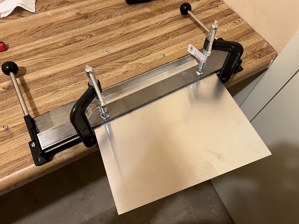
This thing worked great! With some aluminum sheets at hand I was easily able to accommodate the crude shapes I needed. I wont show them all, but here is a large box I constructed for the bottom inverter fan:

The left side is a sort of air intake with a 1″ gap.
Here is the smaller inverter exhaust fan diverter already mounted:

With the aluminum boxes screwed on I am confident now that even sustained water splashes will not destroy my new electrical setup.
July 2022 Update:
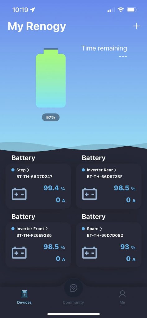
The Renogy “DC Home” app is finally getting a little better. At last it shows the battery id codes so you can actually tell which battery is in what state. And as a bonus lets you name each battery. As you can see I actually bought 4 batteries, but later decided to only use 3. (Ran out of space.) On long trips out west I sometimes carry the spare battery “just in case”.
I bought the ANCOR wire and Marinco stuff at Defender and West Marine ; most of the rest is off Amazon. Here is a list of some of the parts and some additional things I used:
(Links are paid)


Leave a Reply