
Note: This is an older post and I have subsequently upgraded to 300 AH of Renogy Lithium and a Xantrex 3000 XC Pro Inverter. The solar charge controller still works great, I just moved it around!
My new RV came with what I thought was pretty good solar. Only as I learned, it was just fair. There are 4 main issues:
- I can always use more. My van came with 400 watts of solar. 600 would be nicer.
- The GoPower Flex panels, as I learned, are a bit yucky. The biggest problem is that they are glued down to the roof. That creates heat and a limited life, and can be hell on earth to remove.
- The solar controller is cheap bottom of the line. Its a PWM controller that has the chief advantage of being, well, cheap. Its doesn’t work well in overcast skies, for example.
- When I upgraded to Lithium Batteries the solar controller was even less optimal. It worked, but stopped charging before the batteries were topped off.
Especially since I am in the process of installing a compressor fridge, I want/need good solar, so I decided to tackle the controller first.
The SmartSolar MPPT line has great reviews, and I already installed the Victron Battery Monitor made by the same vendor, so it was the logical choice. 30 amp would be plenty. I only choose the 50 amp in case I ever add more panels.
First step is to rip out the goPower solar controller. Its in the most stupid place I can imagine, in the upper cabinet behind the passenger seat. You need a flashlight to read it. Solar controllers are supposed to be placed as close to the batteries as possible, by the way.
This step is pretty easy. You just remove the controller and cap off the wires for now. Then I removed the panel on the right. I decided to cover the overhead hole where the GoPower was with a piece of 1/8″ wood covered with some felt I bought at a fabric store which matched almost perfectly:
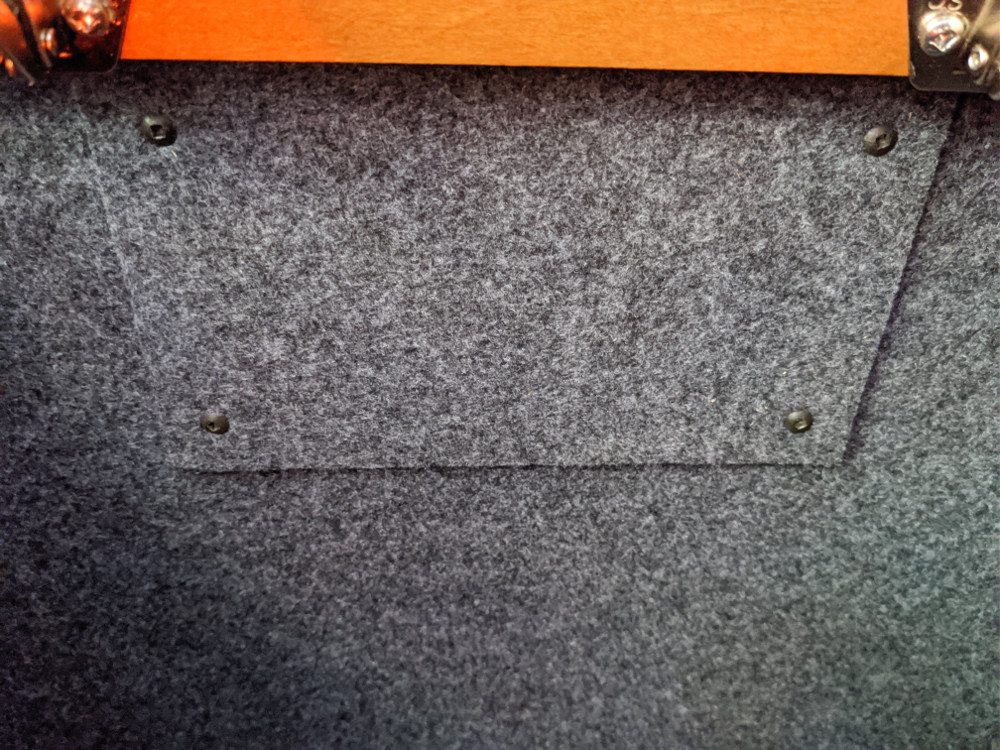
As you can see above it doesn’t look too shabby. No more searching for a flashlight to read the solar meter.
I wanted to mount the new controller next to the inverter, and utilize the existing wiring.
I decided to connect the negatives together and switch the positives. That way I can safely turn off solar when removing the batteries for example.
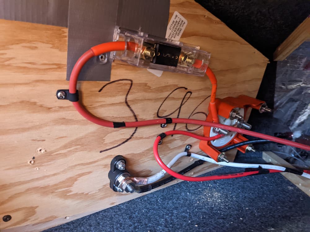
So I removed the side panel of that cabinet and mounted the marine battery switch, which came out like this:
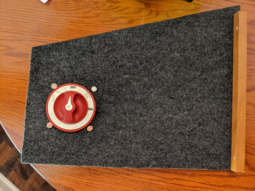
Note that you could just splice the wires together, and deal with a switch or breaker later. But the inverter cabinet is really crowded and it made sense to me to put it here, It also nicely solves the problem of how to splice the 10 gauge input to the 8 gauge output – you don’t have to. Just put a lug on each wire.
You do not need a fuse or breaker coming from the panels, for the simple reason that unless the physical laws of the universe are violated your 100 watt solar panels are not going to put out much more than that, no matter what.
That said, at the last minute I chickened out. If the solar controller were to fry, and short the battery side to the PV side, I guess in theory you could get a lot of amps on the wire. So I ended up installing a fuse behind this switch afterall. This panel is easy to remove if it ever blows, and its exceedingly unlikely anyway. (While fusing should normally be close to the battery preferably I can’t see a realistic scenario where this one is really needed anyway.)
Be careful when drilling the big hole in this panel. LTV put hardly any glue one it, and the drilling bunched up the fabric and tore it right off the panel!
Fortunately the local fabric store had almost exactly the same stuff. A little spray glue, and good as new.
Next, I installed the controller in the inverter bay. Here it is for a test fit, before the install:
Leave enough room on the bottom for the wires to enter. I wanted it low enough to be clear of the inverter reset switch.
Drilling the holes for this is easy if you make a template first, and mark and drill the other side. Use a small pilot hole and a step bit to widen as necisary.
At this point I entered what I call Chinese Crimper Hell. It should be an easy enough task to make professional crimps on the cheap, only it wasn’t.
It turns out most if not all of the cheap crimp tools made are really metric tools relabeled for AWG. The sizes weren’t even close, resulting in over crimping or under crimping.
The crimp is really important. At the very least its a point of potential failure, or at the worst a source of a fire or other catastrophic problem. So it needs to be pretty good.
After buying one hydraulic crimper and one manual one on Amazon, both of which were fake AWG, I settled on a different tactic. First I ordered custom cables for some of the new work.
Where I needed to crimp existing wire, I found an alternative Chinese Crimp Tool that performed an old fashioned punch crimp. These are kind of ugly, but acceptable. Its like hitting it with a hammer. The secret sauce is you can adjust it for the right depth.
So this is what you get with the pin crimper:
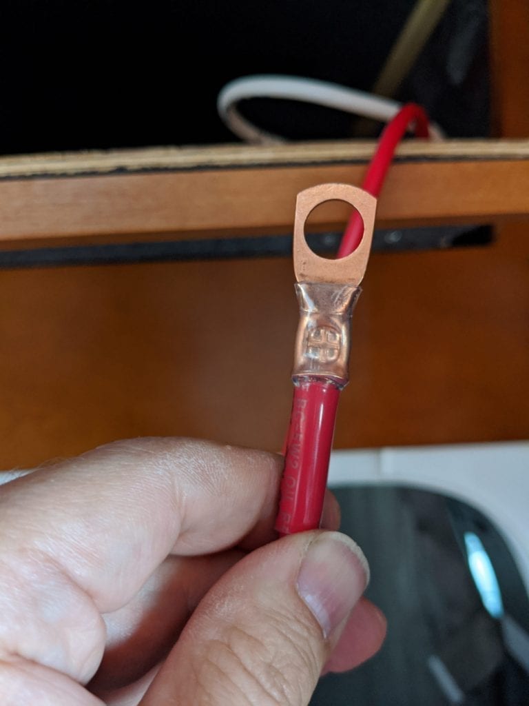
Note that I’ve used clear heat shrink double wall (with glue) tubing, the only kind you should ever buy. People use red or black to hide their ugly crimps, but you want to be able to inspect it in the coming years for corrosion, heat damage, or coming loose. Colored heat shrinks just hide that.
The crimp doesn’t look as nice as the hex crimps but its solid and it works.
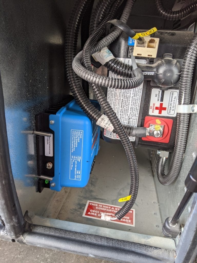
I mounted the SmartSolar and the 30 amp breaker on the output side in the bay and the final result is below:
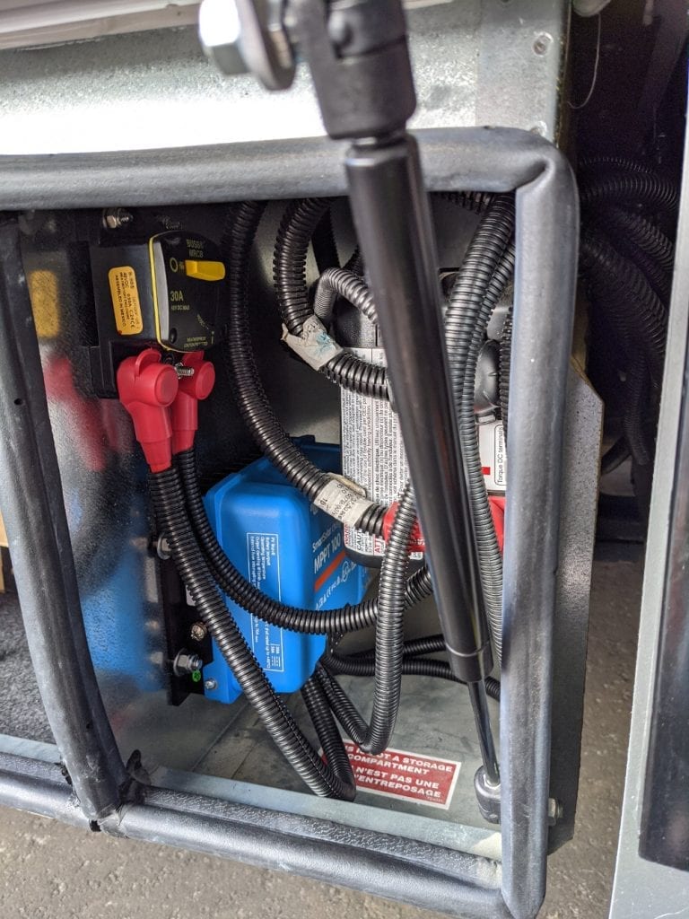
A couple of notes here. I used 6 gauge for everything – bigger is always better. I also covered with wire looms as LTV does. This is really completely unnecessary in a sealed compartment, but it will help prevent rodents from chewing on your prize.
I decided to just piggyback the output (battery) on the nearby inverter as that has a beefy cable run to the battery. Note I also neglected to connect the ground screw which already has a good ground by virtue of its mounting. You should connect it, and I will get around to it.
For the solar wiring, I used 6 AWG Ancor marine wire from West Marine. I ordered 6′ of each, and there was probably about 18″ left over even after I left the wires extra long in case something changes.
Those wires were easy to run into the adjacent battery bay. I just inserted a stick into the void between them on top of all the other wiring with a string attached. There was plenty of room in the existing holes.
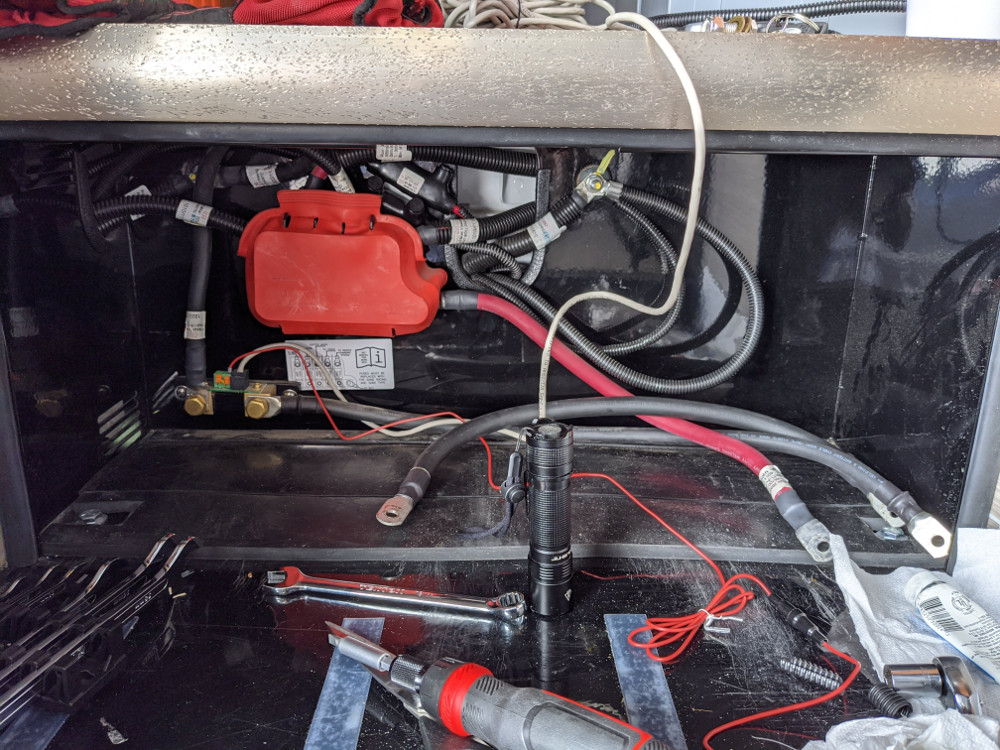
Back in the battery bay, LTV embarrassed themselves by terminating their 8 AWG solar wire into a very small (maybe 12 gauge?) pigtail fuse. So I cut that off, and the ring terminal on the negative. It was too tight in that compartment to get in with a giant crimp tool, and I don’t have any step-down butt splices laying around anyway, so I joined the 6 gauge to the 8 gauge with “Morris” connectors. (Thanks SSTraveler for the tip.)
These are screw down connectors are encased in rubber. In the picture below if you zoom in you can see them just above and to the right of the big red fuse block cover. The can be zip tied to something adjacent for extra security.
I really like these connectors for quick and dirty connections. I was able to tighten them just about as hard as you’d want to go and none stripped.
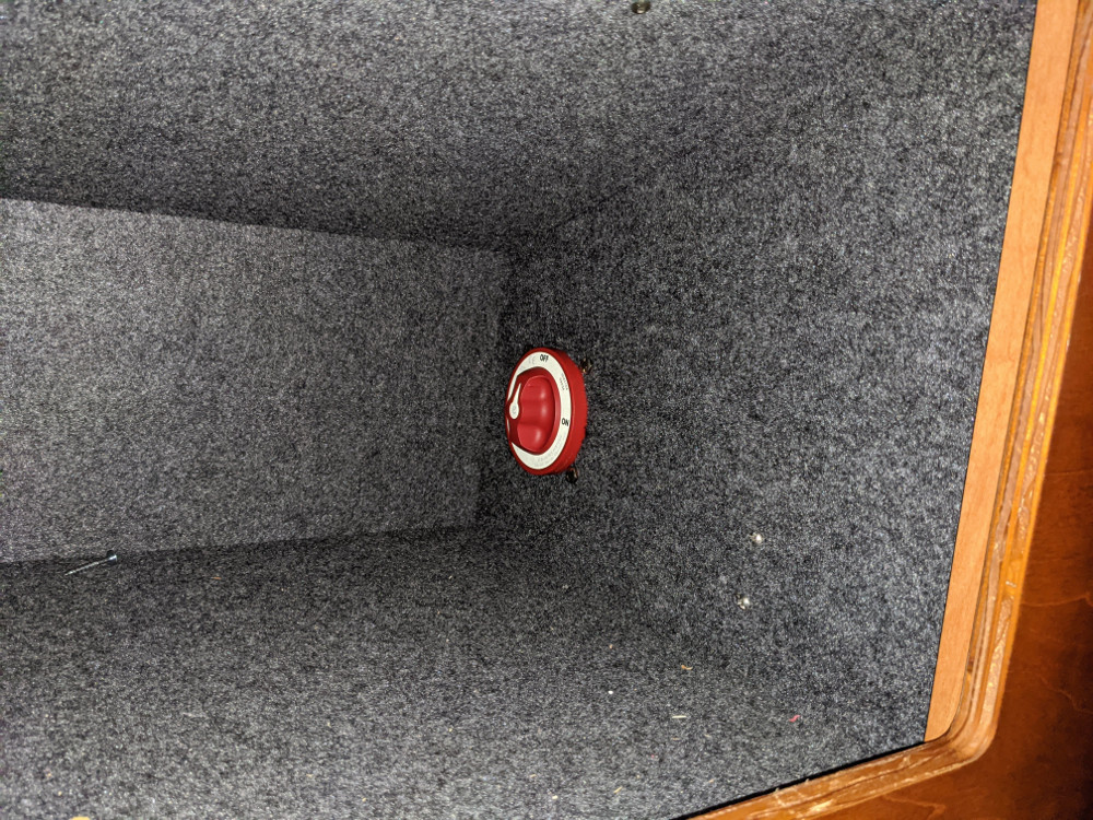
Back to the overhead panel, I wired up the switch. Here is the back.
And front;
Meanwhile, I took a look up on the roof.
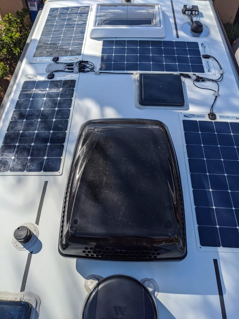
My 4 panels are wired in parallel. For a MPPT controller, most people use series-parallel, where each pair of panels is wired in series and then later combined in parallel.
The advantage is that MPPT controllers work better with a higher voltage. Also, very importantly, the LTV solar wiring is a bit skimpy 8 AWG. Its adequate, but just. Doubling the voltage will halve the amps, making the existing wire more efficient.
The main reason not to wire all 4 panels in series is that if one fails your entire solar farm goes out.
Rewiring the solar is actually quite easy to do, although confusing at first. Sometimes I need to visualize stuff so I drew myself a diagram of how I wanted it to end up:
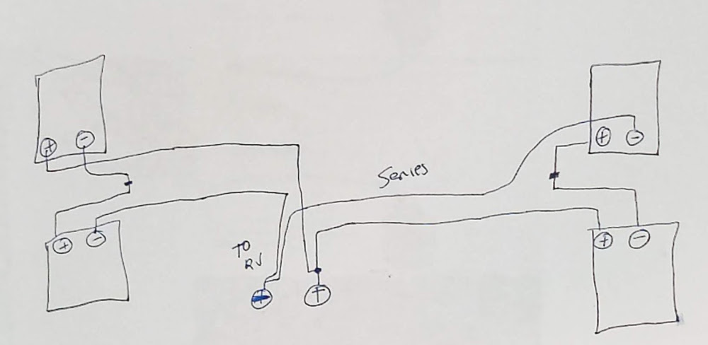
So for my van this means the only thing I need to do is unplug the positive of one of the cells on each side of the RV, and the negative of the other, and connect them together! Then, as you can see, each pair is wired in series and lastly paralleled.
(Don’t wire each pair in parallel – and then later do the series. That will work just fine, but a single cell will knock out the whole solar.)
So here are the results:
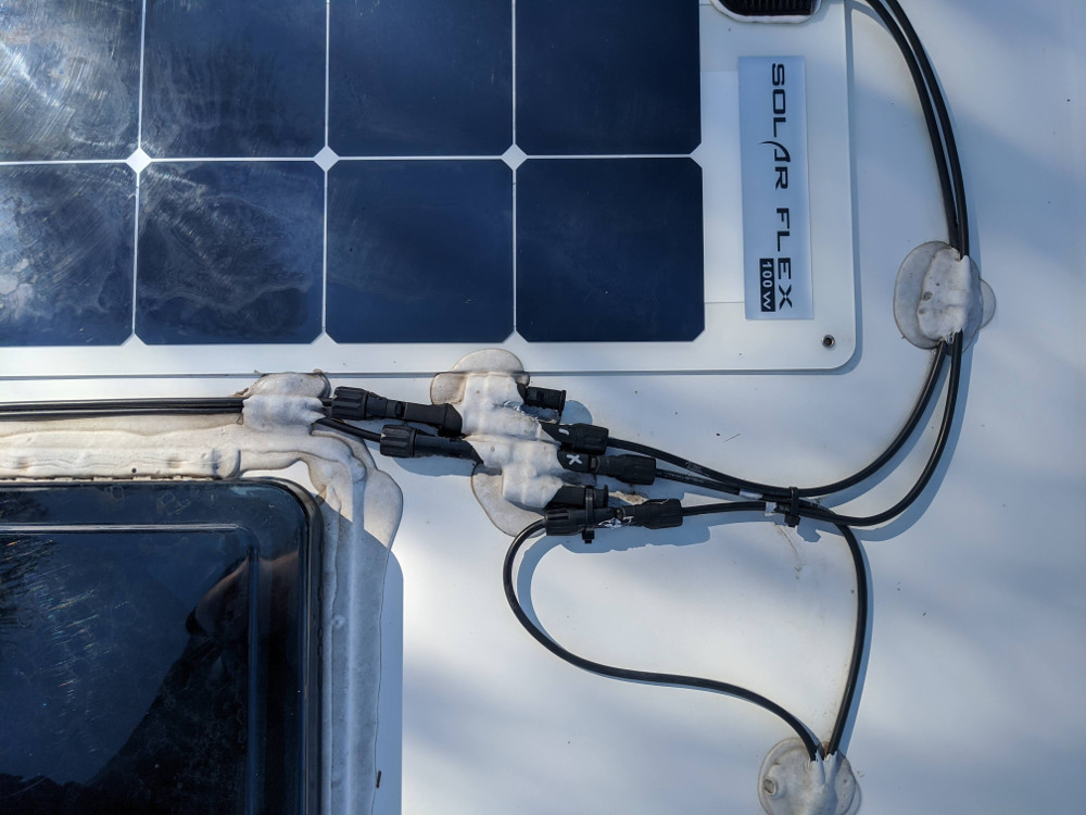
The first picture above, is the right side of my RV. All I had to do was disconnect one positive and one negative from the branch “combiner” MC4 fitting, and then connect them together. The unused port on the branch connector is fitted with a dust cap.
To unplug the solar, I first made sure I was parked under a roof, which is good enough, although you are supposed to cover the cells.
Then use a zip tie around the release, as you probably cant get your tool under a branch connector that’s dicored to the roof. Just pick one positive, and one negative and connect them together.
I used the zip tie and some scraping to punch through the dicor and get under the connector release on some.
I’m left with a slightly sloppy installation. The branch connectors now have unused ports. But it’s good enough, and I plan on replacing my panels with rigid someday anyway, so why bother to redo the wiring.
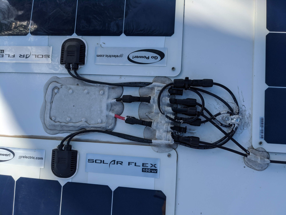
The other side is pretty much the same thing, only here you have 3-1 branch connectors, so again, I just chose one positive and one negative. That little cable clamp on the right was holding everything down too tight, so I scraped off the dicor and removed the cable to unwind one loop. I’ll clean this up later and replace the cable clamp and dicor over to protect the screw hole, but this is good enough for testing.
To avoid stressing the cells, while I was doing this I turned off the connection to the charge controller. I then unhooked the cells on both sides, then connected them. By doing it this way, When I connected the right pair in series first the left pair was disconnected.
Nothing will blow up if you connect a cells pairs of different voltages, but nothing wrong with doing it methodically in my view.
When I went downstairs and turned on the disconnect switch to the roof I was rewarded with this:
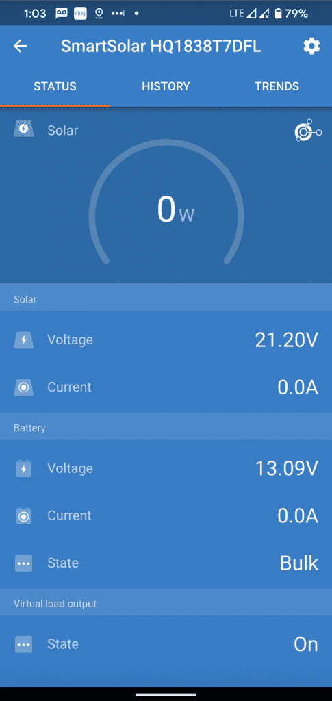
So even completely under roof, the SmartSolar was struggling to try to do its job and even went in to bulk charging mode and churned out 1 watt occasionally!
Next, off for a drive in the sun and everything seems to work OK. My final task it to drain the battery down and go do a comprehensive test on a sunny day and see how I’m doing. My first venture into the sun I was getting 35 volts on the PV side so at least I know the wiring is correct. I’ll update the results of further testing soon.
Here are links to at the products. Besides the Amazon items below I ordered 6 Gauge Ancor Marine wire. I also had a couple cables custom made at BatteryCablesUsa.com. The dust caps and plugs I got straight from China.
Update: Feb 23 2020
Here in Florida in the winter, the angle of the sun is all wrong, so you don’t get much solar. Even so, I occasionally pull close to 300 watts in peak sun, so thats realistically the most I can expect.
I’m particularly impressed how much energy I get on overcast or even shade.
So no complaints so far…
(Paid Links)


Leave a Reply