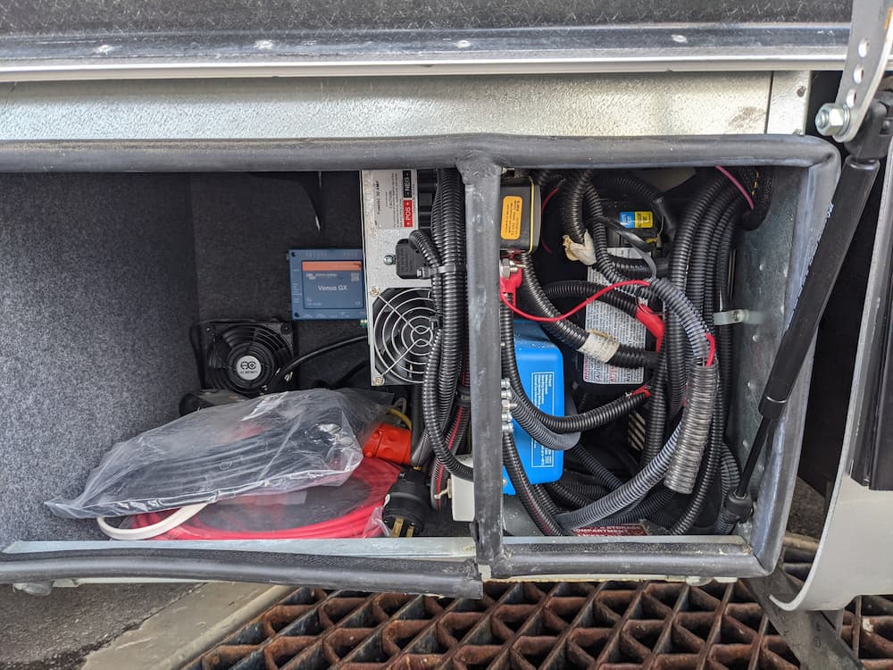
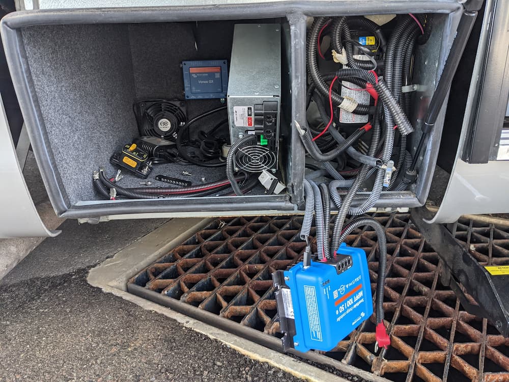
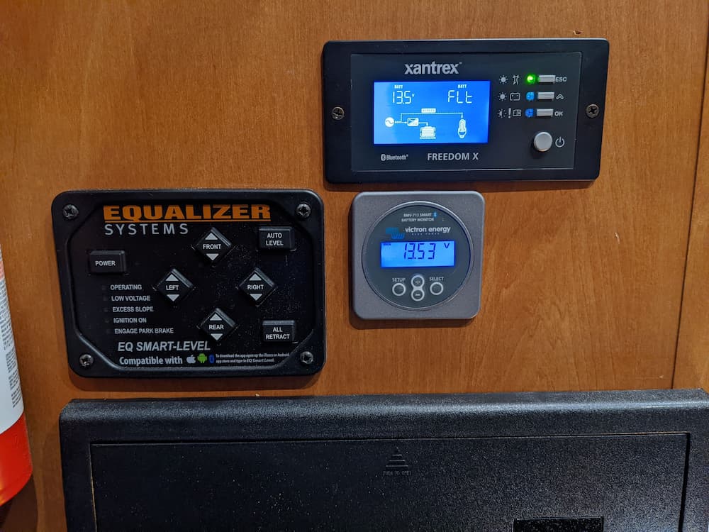
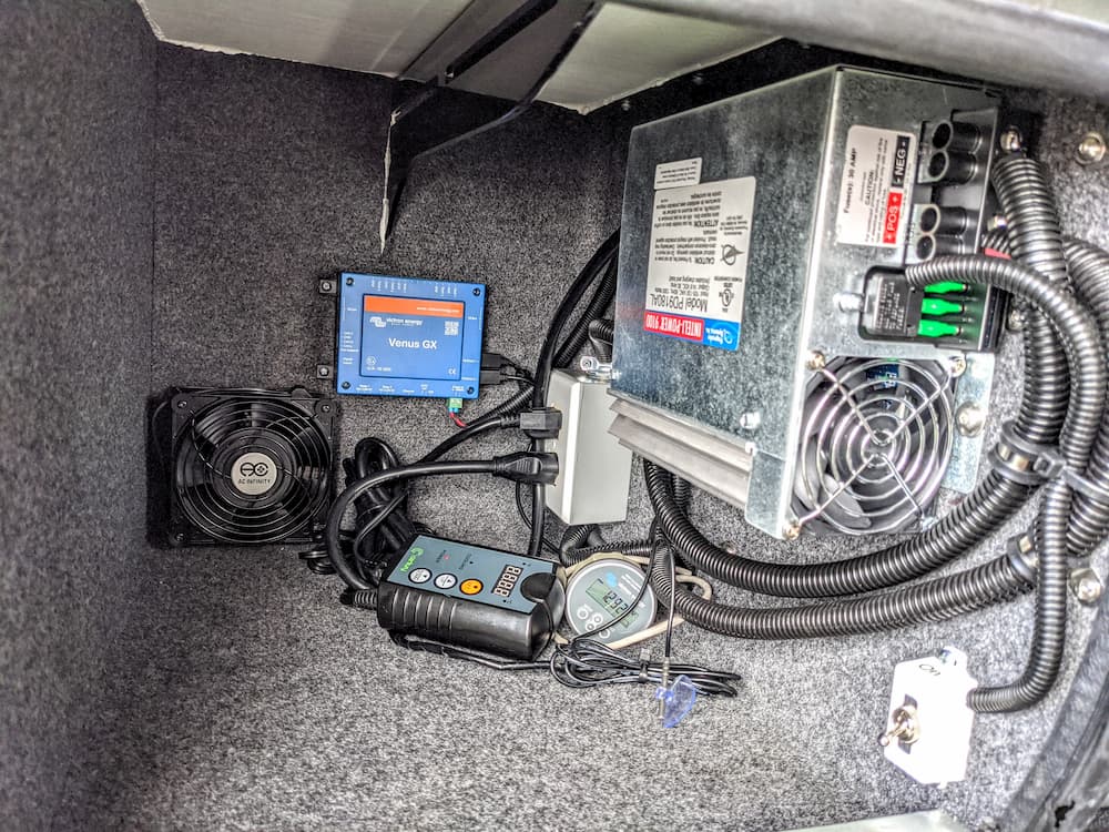
Most of the DC gear in my RV is Victron – the BMS 712, 50 amp solar MPPT controller, and an old Venus to connect to Victron VRM (remote Internet monitoring).
I always wanted a Victron Inverter/Charger but I don’t have the space, location, or weight capacity to mount one, so I settled on a Xantrex XC 3000 Pro.
The Xantrex has worked very well but does not have any sort of remote monitoring.
Except – over time they (Xantrex) have updated it to have CAN bus / RV-C support so in theory it can talk to Victron, and even display live status info and controls on a Victron app or touch screen. The only thing missing is a (big) program to do this trick. I figured I would write one.
Right around the time I started looking to see if I could do that, I discovered that somebody already had!
So, what I found was not only was this possible, but Scott has a (mostly) working version already running. I got in touch with Scott and volunteered to do some testing. I found his program incredibly complete and useful, but a some sections he had not 100% finished. I recommended some patches after testing and Scott came through with some quick improvements, mainly on displaying charging information. Thanks Scott!
At the link above, Scott gives instructions on connecting the CAN bus from the Xantrex to a USB converter and to a Raspberry Pi, but I just want to connect it directly to my Cerbo GX. (I just bought a new Cerbo GX to replace the old Venus)
I started with this article by Victron to gain root access to a Cerbo type device. Venus Root Instructions
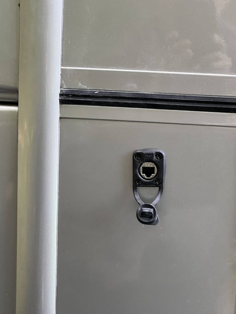
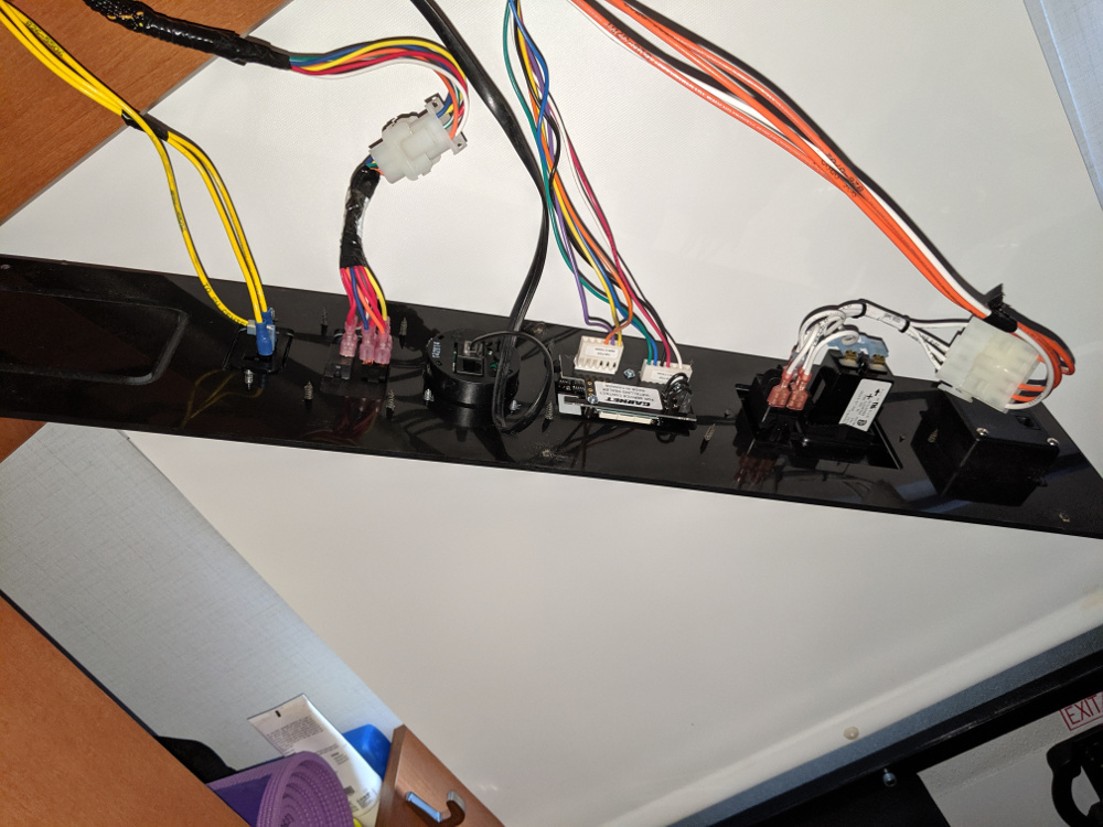
Then I figured out I just needed to connect 3 wires from an RJ45 to the 20 pin Molex connector that is standard on the Xantrex XC Pro models.
Lets start with the Xantrex Molex Connector.
So, we just need to connect 3 wires to the Xantrex:
12. CAN ground
11. CAN high
1. CAN Low
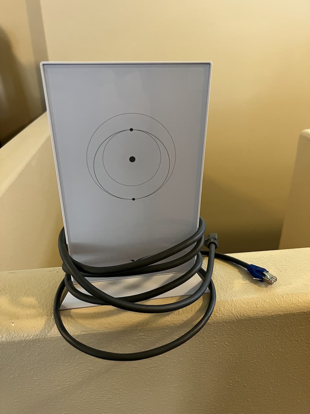
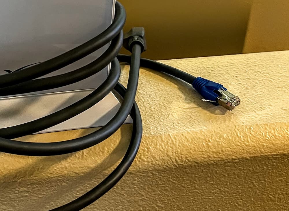
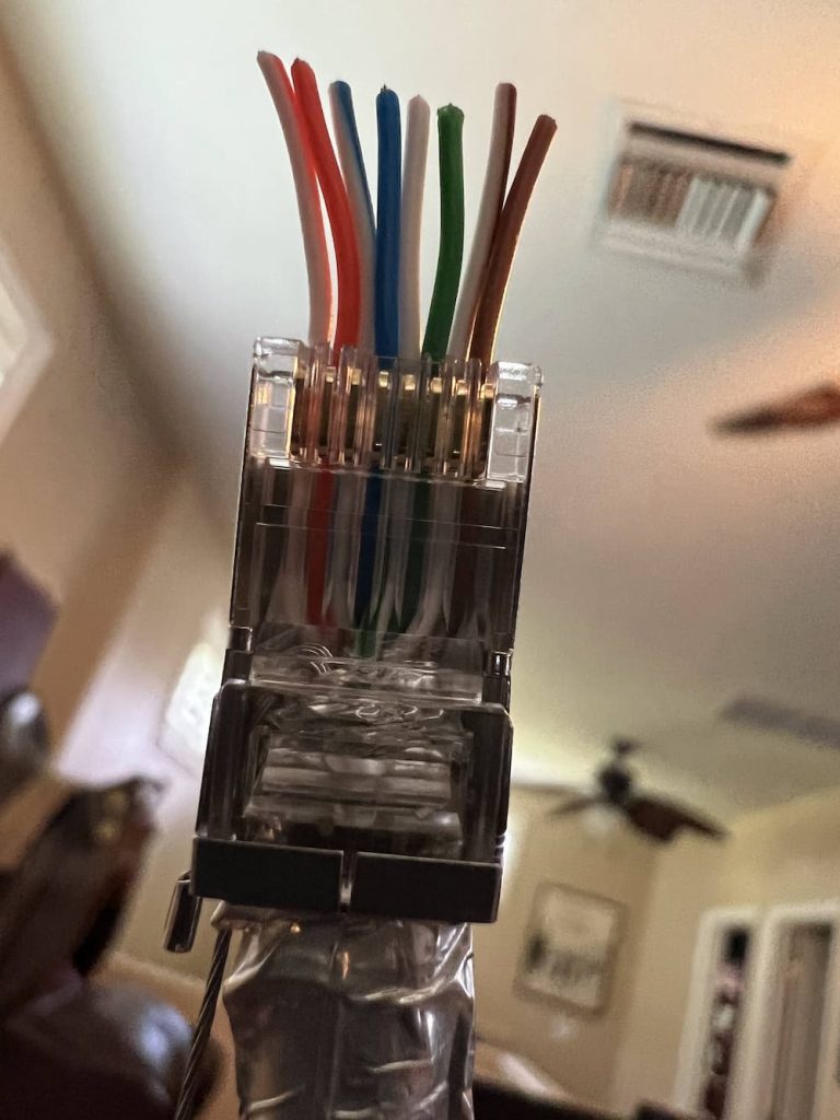
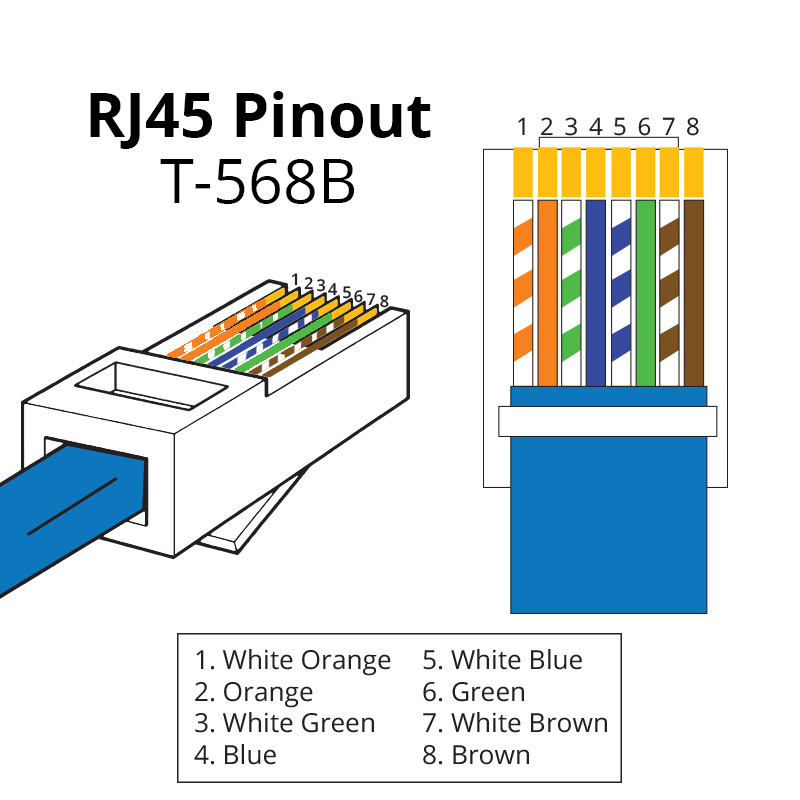
Over on the Cerbo, the CAN ports are RJ45 jacks. So I just took a random network cable laying around, and cut off one end. As far as figuring out how to pin it, lets look at the Victron documentation:
This shows us that we will be using pins 3,8, and 7. Note that the colors listed above were right in my case, but don’t depend on that always being true as there are at least 2 network wiring standards that I know of. So I looked carefully at the RJ45 to verify I had pins 3,8, and 7.
I hate trying to crimp Molex pins these days – they are too tiny for me to see easily, so I just keep a box of Molex prewired pins on hand with a bunch of random sized Molex connectors. So I just grabbed 3 wires, pushed them into a 20 pin connector, snipped off the other end, and temporarily crimped them to the appropriate RJ45 wire. (Later, for the permanent RV run, I will solder up a nicer splice.)
Next, I updated my Xantrex PRO completely. By that I mean all three updates – Main, Bluetooth remote, and the “Communication Interface”. Unless they are all running the latest firmware you will not have good results. These are all available from Xantrex. As an aside follow the instructions very carefully as its quite possible to brick your Xantrex if you really mangle this, like turning it off while its updating.
And finally make sure your Cerbo, Venus, or Raspberry Pi is likewise running the very latest version.
Then I:
Created /data/xantrex-service
Placed Scott’s program there
Downloaded the Venus library per his instructions
Started his program
And, amazingly it works! I now have the Xantrex reporting status (somewhat) accurately on my Cerbo.
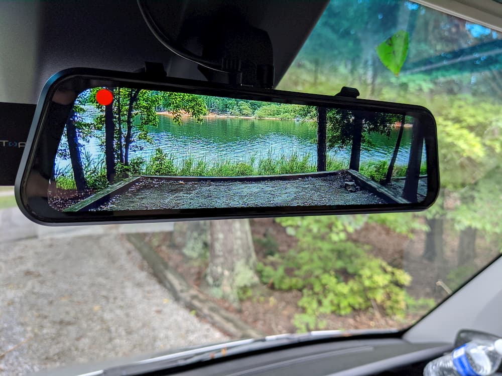
As an aside, I always wanted the Cerbo remote display but find it impractical as it requires an HDMI cable and is expensive. Then I stumbled on to this beauty:
These instructions detail the procedure to turn a cheap Android tablet into a GX display, over local Wifi, so no wiring!
You might be wondering why bother to do this, as any device can be a GX display. But this puts a tablet in “Kiosk” mode and hardwires it as a display, so its always running and you won’t have to login periodically.
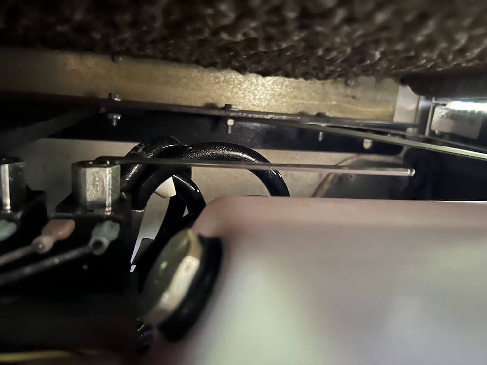
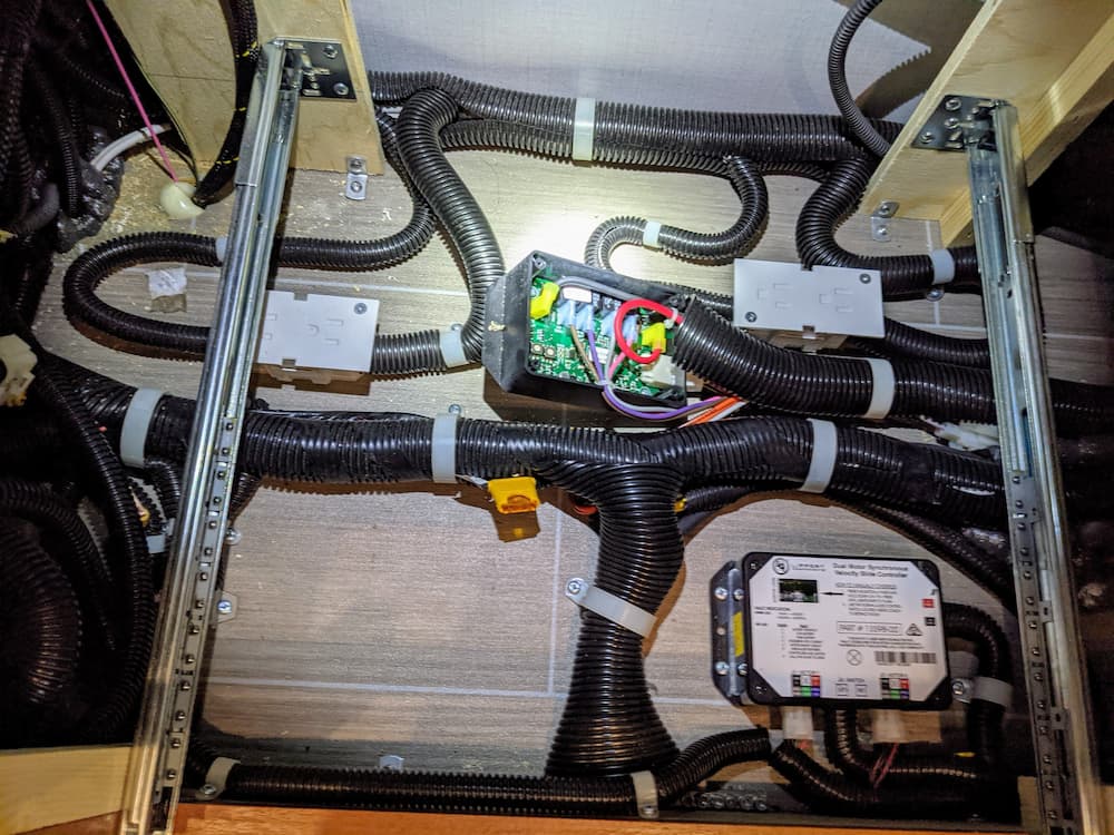
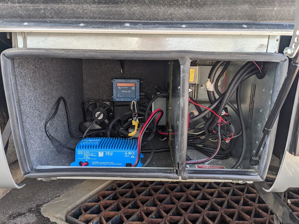
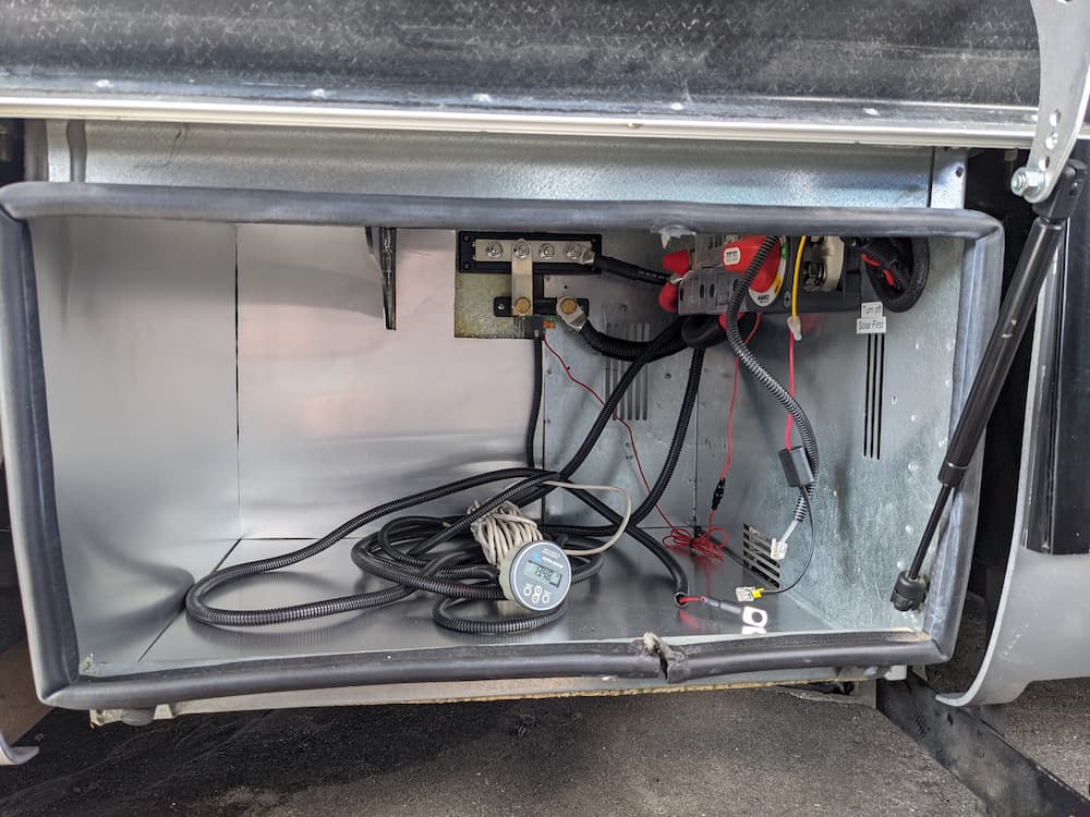
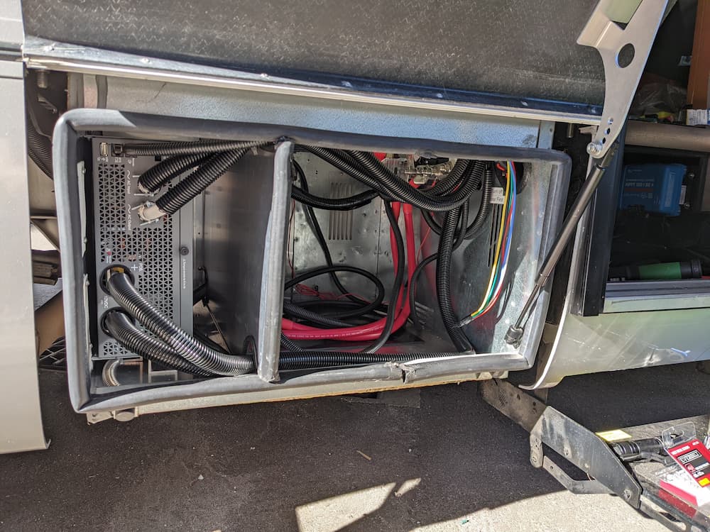
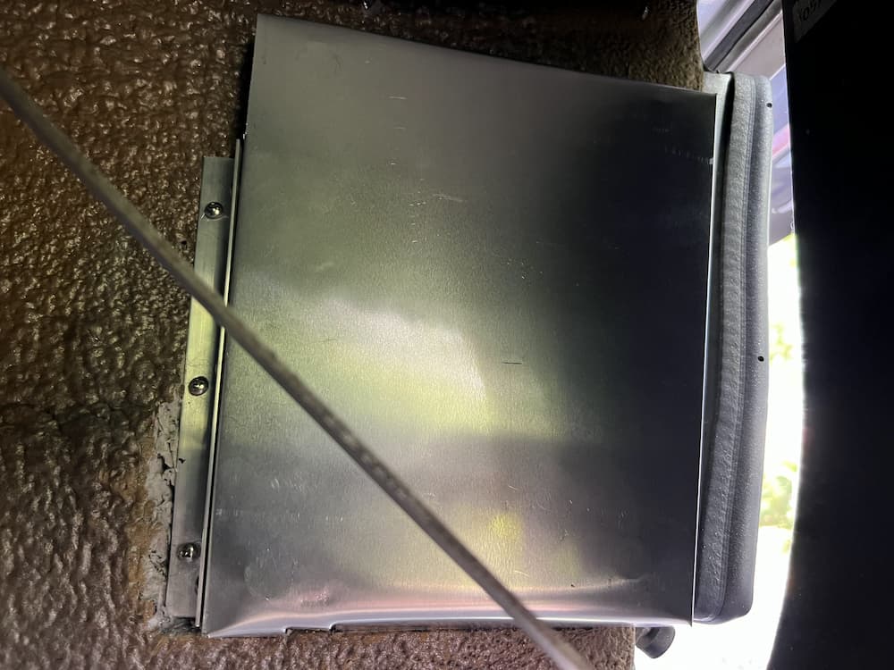
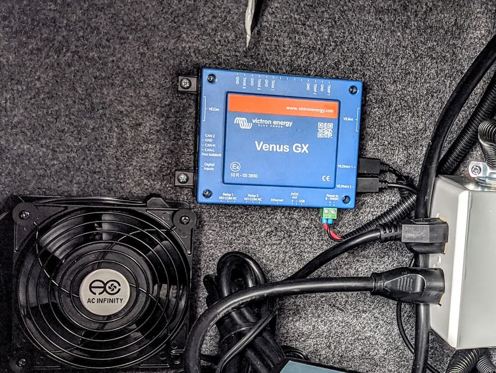
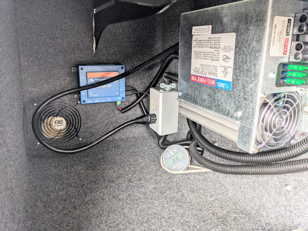
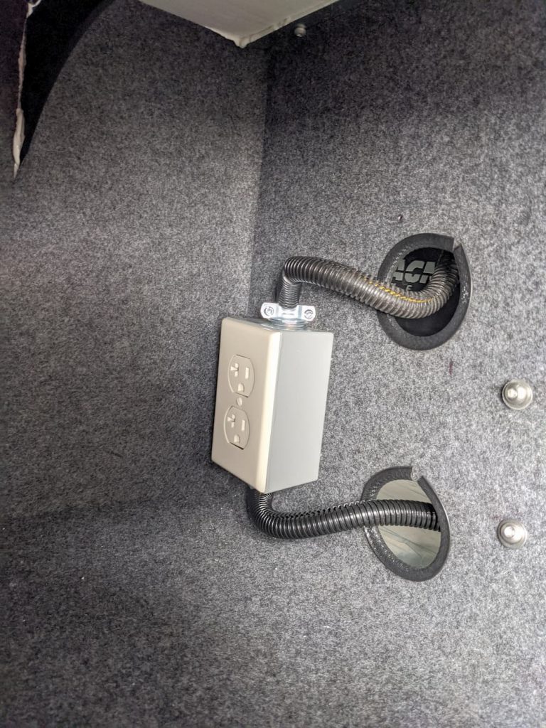
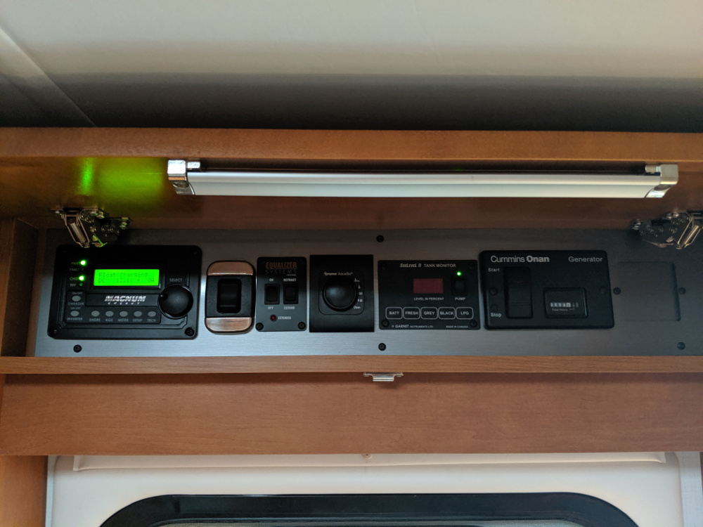
Now, back to my RV a while later, I mounted my new Cerbo (upside down, as that was all I had room for). Fitting as my inverter is likewise upside down.
I made a custom RJ45 cable just because I had a roll of CAT6 and the tools laying around, and except for a few zip ties and some cleaning up of the wiring above, this is basically it. Plugged into the Xantrex and everything works as expected.
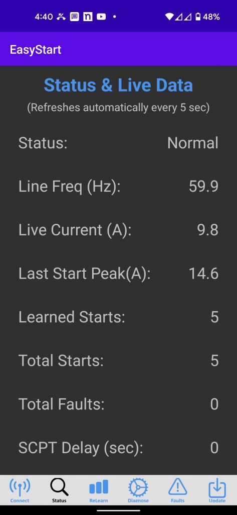
For the first time I can see the Inverter mode, and the AC load. Clicking on the Inverter gives some additional information but not a lot yet.
In the future I hope to continue tinkering with the program to allow me to remotely control the charge rate and float voltage, settings I change often, but for now this is a great little remote upgrade that lets me spy on the Inverter from anywhere in the world.
To permanently install Scott’s program and automatically restart, I created start.sh in /data/xantrex-monitor:
#!/bin/bash cd /data/xantrex-monitor nohup python3 xantrex-service.py –can vecan1 &
(Adjust can port for your installation) Make the script executable and link to auto-restart:
After that whenever the Cerbo reboots the Xantrex service starts automatically. Here are a few parts I used for this installation including the Cerbo itself:
Links are Paid. Click on a link to see product at Amazon.
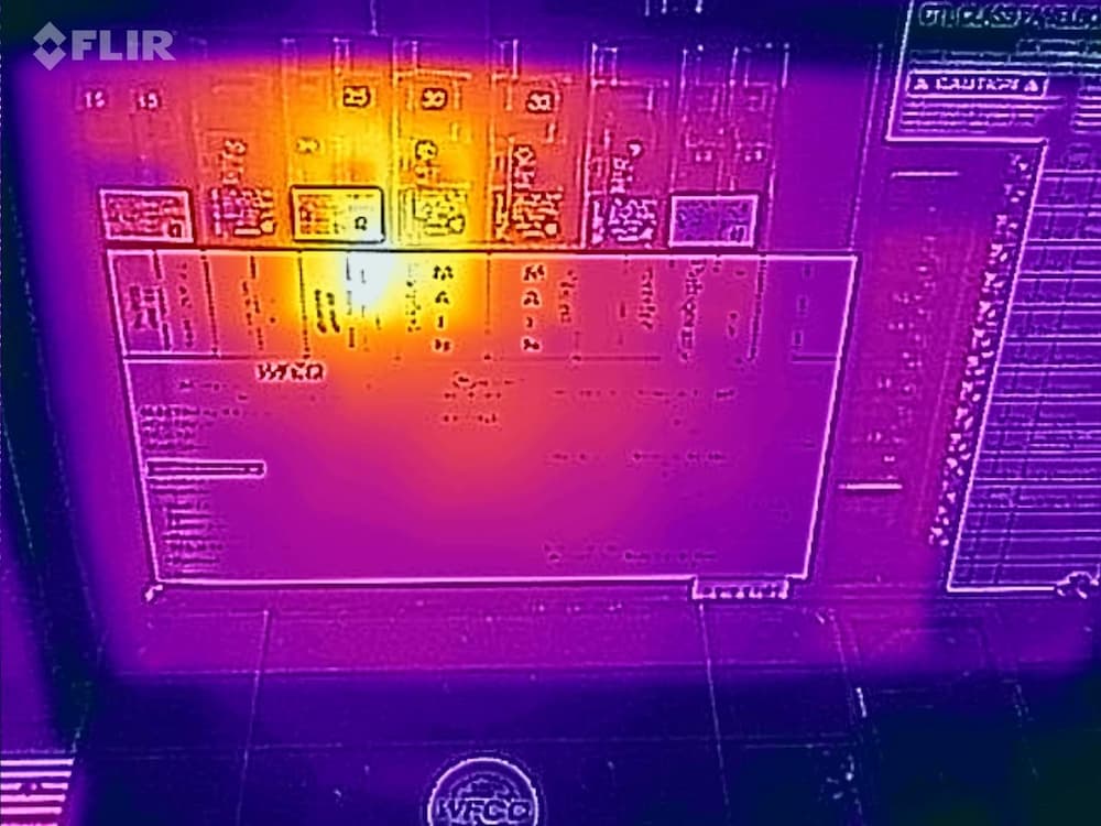
Well into my trip to Canada I encountered the dreaded “08” and “07” errors on my Xantrex Inverter. This indicates at least one of the fans has failed. In my case, and probably most cases, the fan hasn’t actually failed – the tachometer signal the fan sends back to the Inverter to prove its running – stopped working.
This is a pretty catastrophic error. The Xantrex goes into “bypass mode” (so you can still use generator or shore power) but you loose the inverter and battery charger.
Fortunately, I have an onboard Victron 25 amp battery charger that’s wired permanently and I’ve never actually used in 4 years. So I just had to turn on its breaker and at least I had a small shore power charger again.
Since my inverter is quite difficult to remove (have to pull both batteries first) and since I was in Canada at the end of my trip anyway, we just headed home.
Reminded me of the old days – starting the generator at a rest stop to make coffee!
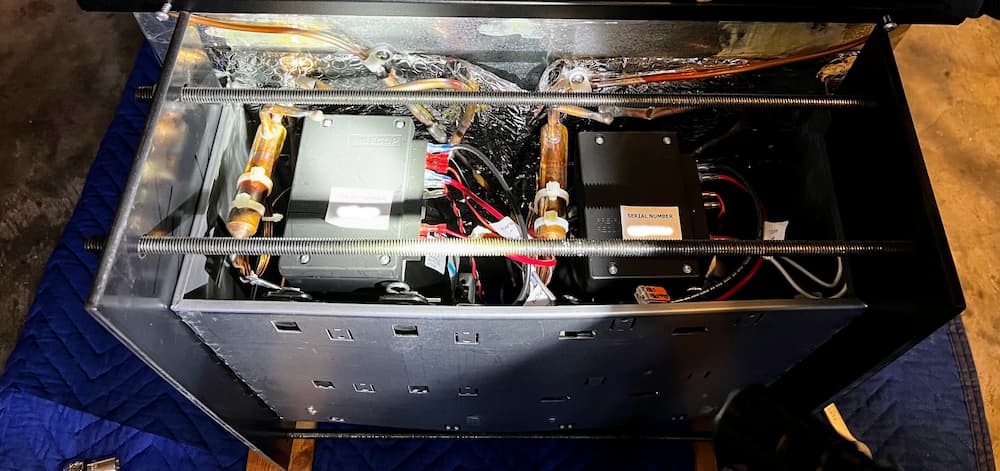
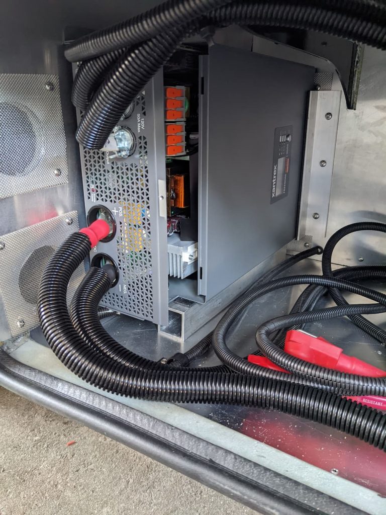
Once home, I pulled the Xantrex out and started examining it. the case is secured with many small screws. The bigger one has a round sticker over it, and likewise the date code on the other side has a small screw under it. (Obviously you are voiding your warranty)
From online reports, Xantrex tells customers to throw the Inverter in the trash when the fan fails. Hopefully this is an easy fix.
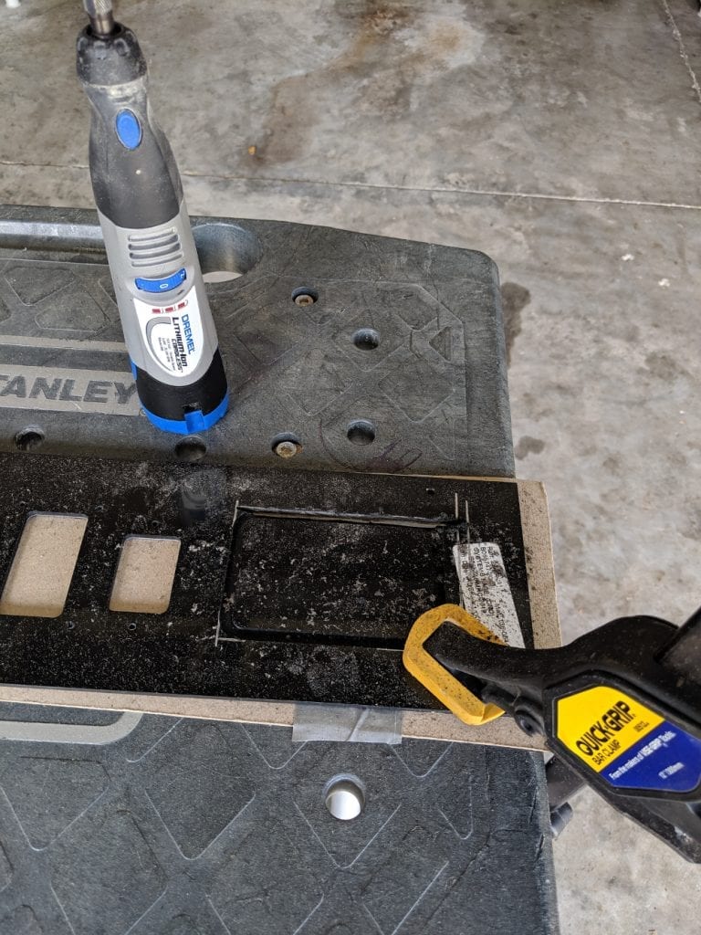
Once you get all the screws off, gently open the top and rest behind the Xantrex.
The circuits are all protected by the paper guard you see above. I had already cut a few zip ties and peeled back the top part to expose the fans so I could get a part number. I subsequently decided to make two scissors cuts so I could remove the guard. I didn’t see any need to remove the cover or disconnect all the wires that are not really in the way.
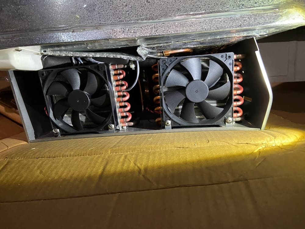
The fans are easily removed. These are the culprits:
A Google search shows these are really rare fans. I found them on the Chinese manufacturer website and also a Hungarian website. Although one or both had failed, they have been spinning for 4 years outside so I really can’t complain. But I didn’t want to wait weeks for a replacement to ship (not to mention the [shudder] tariff these days) – so I started looking for a replacement.
These are 92mm X 25mm fans so not that hard to find. I used chatGPT to search for replacements and here is one of these sessions:
So in the chart above the first entry is the Xantrex OEM fan, the second is a common fan available immediately on Amazon, and the last (and the ones I chose) a higher quality industrial fan not usually sold on consumer sites like Amazon but available on Mouser.
I chose the Delta because its a solid fan and its airflow is significantly higher than the OEM fan (which is already a beast). The Arctic fan in the middle of the chart (recommened by an excellent video I found online) was available on Amazon Prime, but both the Airflow and current were significantly lower. This causes me to suspect I would experience issues in extreme conditions which I encounter sometimes in the summer heat.
The Delta fans are real monsters for this size, and louder. But the fans only run on full speed when needed, and are barely audible in the coach, so I can live with that.
I overnighted them (ouch) from Mouser (link below) and they showed up bulk wrapped with no connector. Which is great, as the Xantrex uses a non-standard 3 wire plug anyway – which is skinnier than standard PC fan plugs. So I had to cut the connector off the Xantrex fans and solder 3 wires on each to the new fans. The 4th (PWM lead) is not used.
Note that Delta uses Blue for the tachometer, so the wiring is red to red, black to black, and yellow to blue.
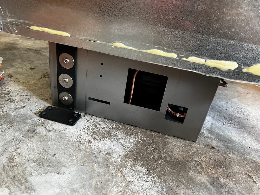
I used “Western Union” splices and solder, covered with heat shrink tubing and zip tied for safety. This picture shows the new fans installed.
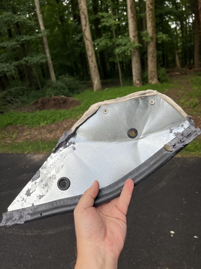
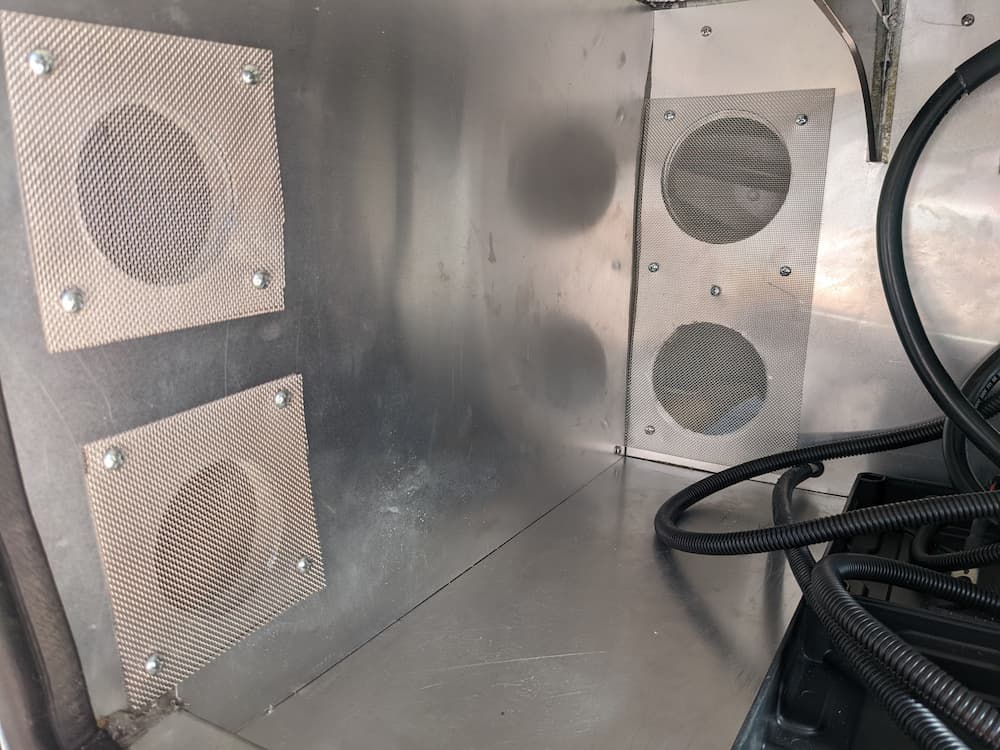
The grills were rusted, so I also installed new fan grills. This is the exterior view:
To test it, I just connected a standard AC cord:
I plugged it in and it worked great! These turbo fans really do push some air. You get an error initially as there is no battery present but then eventually it settles down, spinds down the fans, and its ready for reinstall.
So this failure has a happy ending. For a small amount of money I got enhanced cooling and reliability, and we are off and running again.
Here are some useful parts. The fans are available at Mouser If Mouser is out, the Amazon Link below may have stock:
<Links are Paid>
Delta 92x92x25mm 12 Volt High Speed 4 Pin PWM with Tac Sensor Fan AFC0
Victron 25 amp charger
Bergen Industries Inc PS615143 3-Wire Appliance and Power Tool Cord, 6
Easycargo 2pcs 92mm Fan Grill 92mm Guard Black with Screws (92mm)
SummitLink 410 Pcs Assorted Heat Shrink Tubing Wrap Sleeve Set Combo T
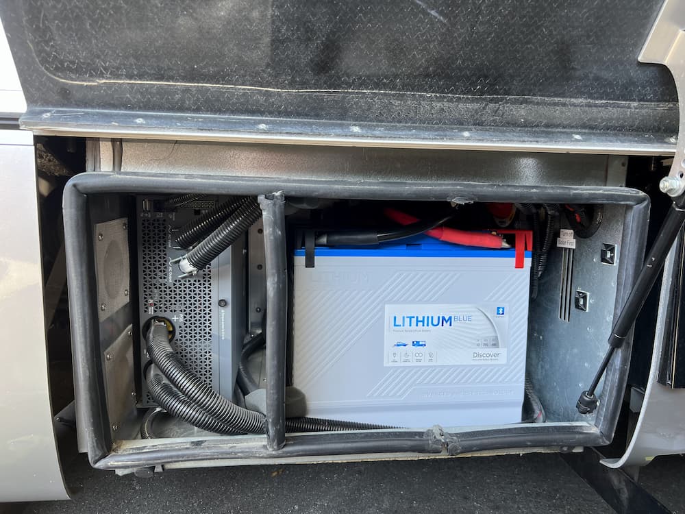
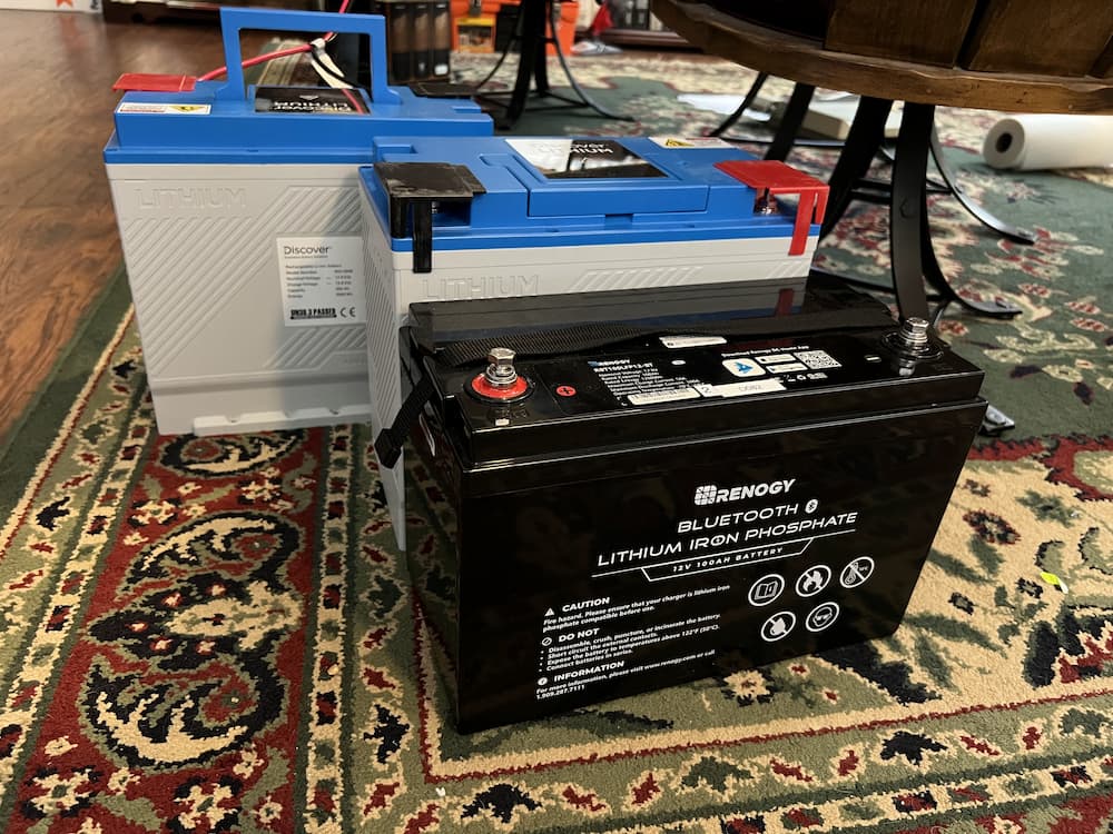
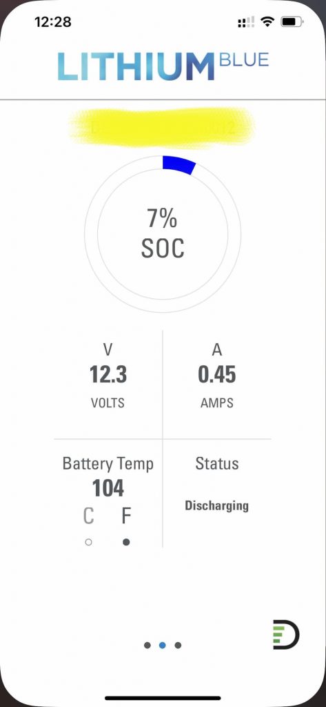
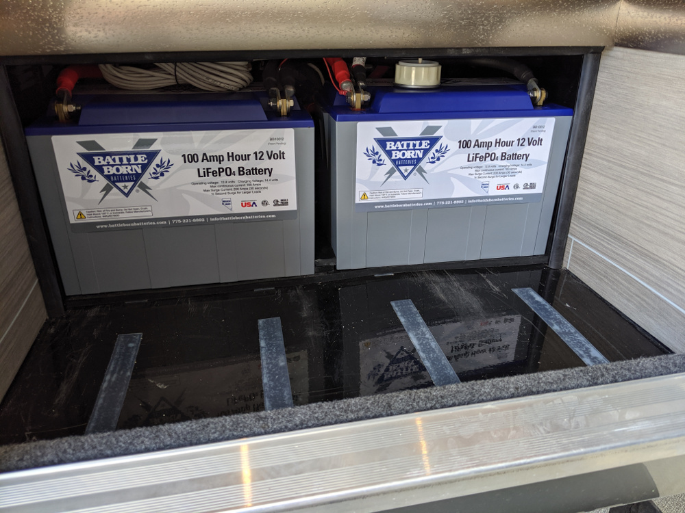
The Epoch 300 is so popular that they are literally everywhere. And for good reason. It’s a high quality budget battery made by Roypow, which is a Chinese conglomerate with a good reputation. It normally sells for $995 but with the Black Friday sale after thanksgiving I purchased mine for just $799 each. The price, quality reputation plus their diminutive size, made them a no-brainer for me. I got them ahead of any tariffs coming which may affect pricing in the future. $1600 for 600 amp hours is incredibly cheap compared to just a few years ago when the equivalent Battleborns would have come to $6000.
For starters my Discover Blue 200’s are going to be a tough act to follow. These batteries have a bunch of killer features almost never seen in lithium batteries. A user replaceable BMS, built in terminal fuses, and screw down simplicity to begin with. The Epoch has none of these, but packs 50% more spinning electrons in (roughly) the same package size, so I am willing to forego some convenience to raise my battery farm from 400 AH to 600 AH.
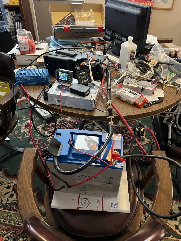
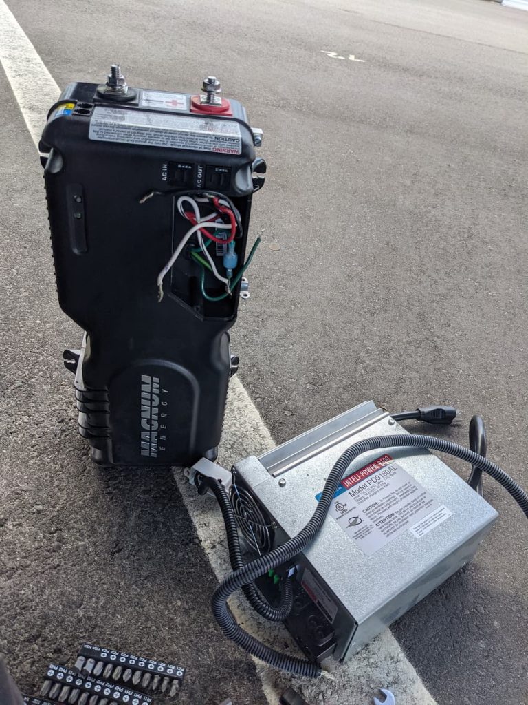
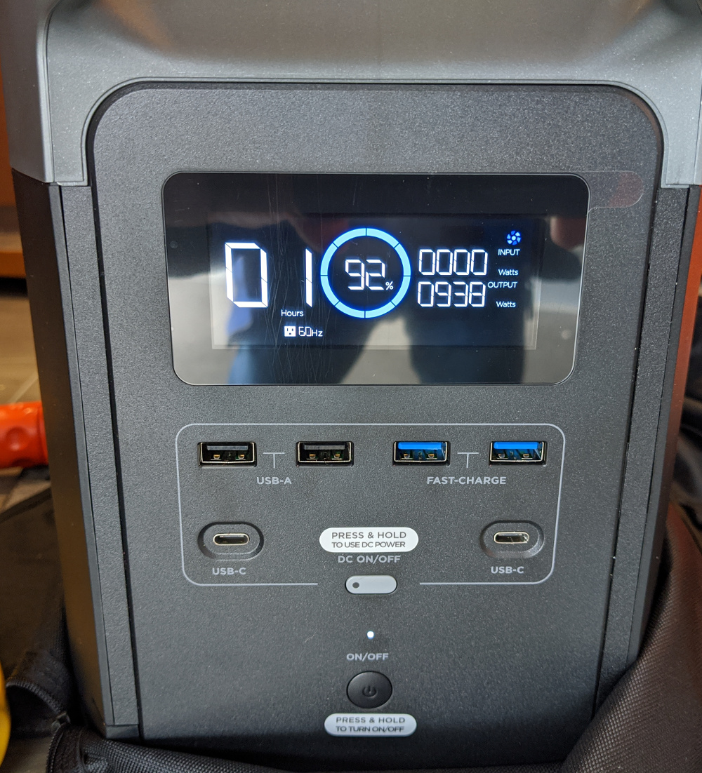
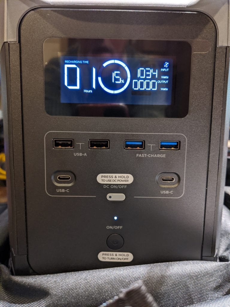
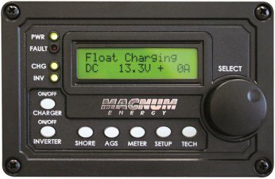
I always start with a full capacity test to make sure the batteries are working properly. So using my old Magnum inverter, a small Vicron charger, and a cheap battery shunt off Amazon, I fully discharged each battery to around 4% to be sure all is good. I’m too lazy to go through all the bother of installing these only to discover one was damaged internally by being dropped by Fedex. For testing I used a hair dryer set on low, which is around 750 watts.
As expected they worked great.
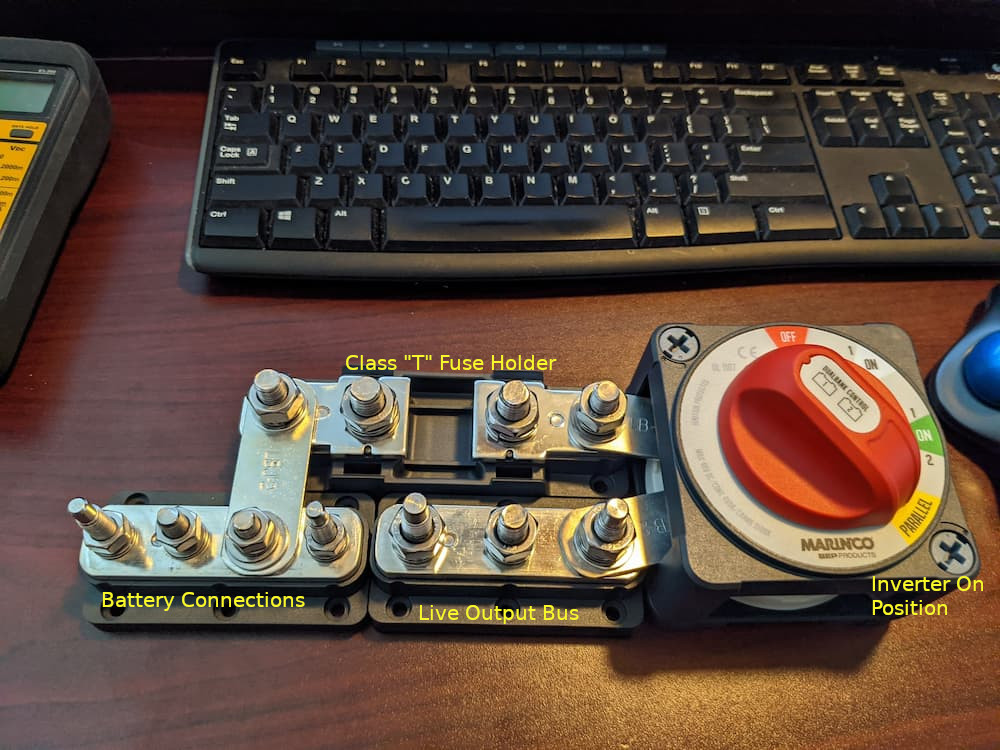
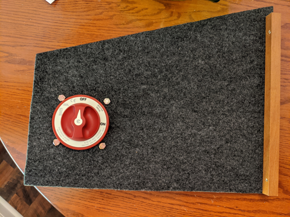
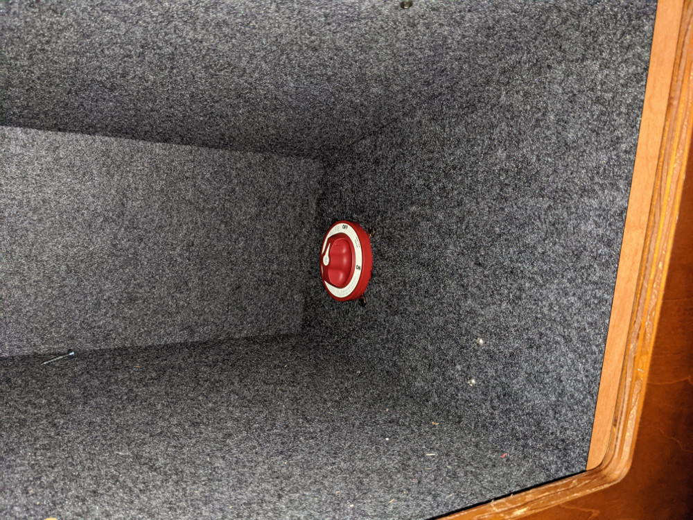
For background info, I use some clever Marinco products to simplify and improve installation. The genius of the BEP line is that these products all connect together using heavy duty busbars. (Links to products below).
On my desk, it looks like this:
Originally I designed this for 3 batteries but for now I am using only 2. If you follow the battery bus bar, it leads to the class “T” 350 A fuse. That connects to the switch, so you can easily turn off 100% of the rig for safe long term storage with no parasitic drains.
The first 2 switch positions are both “ON” but the “Parallel” click is where the inverter is connected. You can’t see it in the picture but the inverter is connected where the switch says “Parallel” with huge 4/0 wire. So there is another safety/convenience feature here that unless you click down to “Parallel” the Inverter is 100% disconnected from 12 volts, which is useful for storage or maintenance.
So in one convenient package here we have the ability to switch off batteries and/or inverter and all without any wires.
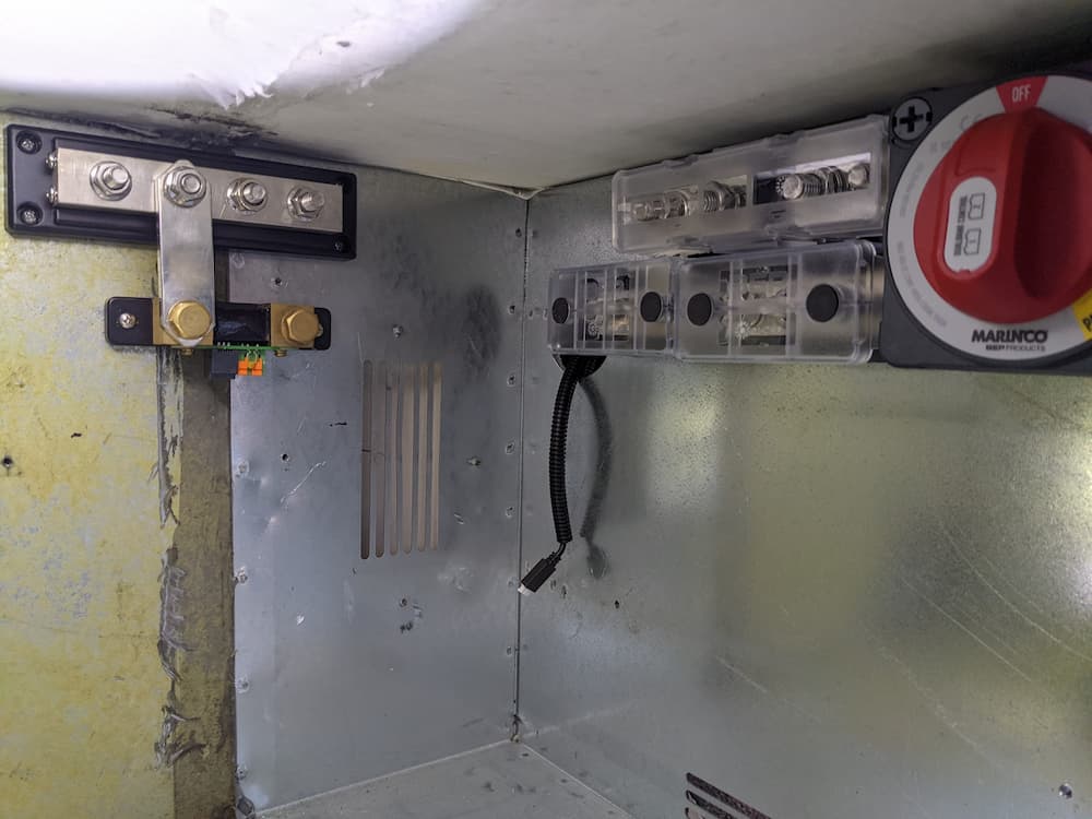
Mounted, it looks like this:
The “bus bar” method is the safest and best way to interconnect batteries. Each battery will have a terminal mounted Blue Seas 250 A fuse and use 2/0 wire.
The connections to the Marinco assembly above use 4/0 wire as they carry the aggregate current. The class “T” fuse is conservatively rated at 350 amps which is less than the 2 batteries can continuously produce but much more than I could ever be wanting to use at once. It also keeps it around the 300 amp continuous rating of the factory installed Bussman Mega fuse holder.
So on to the batteries themselves. I added Blue Seas 250 amps terminal style battery fuses so each battery is individually fused. This protects a high load or dead short in one battery from ruining the other one hopefully. (I never trust high current overload shutdown after the Lithionics debacle where they were found to melt internally under high load.) While the Lithionics failures were particularly egregious, Will Prowse has pointed out this feature is not always reliable on other batteries as well due to software errors or just poor design.
I bought a 4 foot long piece of aluminum 1″ angle stock from Home Depot, and cut sections to use as battery mounts. It is extremely important that these batteries be mounted permanently and rigidly to prevent vibration damage or worse (like a fire from loose connections). Also a 1″ flat aluminum bar to hold down the top, with some Amazon “J Hooks” holding it down.
If you look under the hood at a modern car the battery is typically housed in a metal box and held down with bolts. If you look at a typical aftermarket house battery mounted in an RV by the owner, not so much. I’ve seen everything from nothing to packing foam blocks to string being used, none which works as well as metal.
The greatest challenge by far is mounting these in a small enclosure! I sure wish battery makers would take a hint and add screw mounts like my Discover batteries. But lacking that, I bought some Home Depot Aluminum 1″ angle stock. Its hard to see in the other pics so I zoomed in:
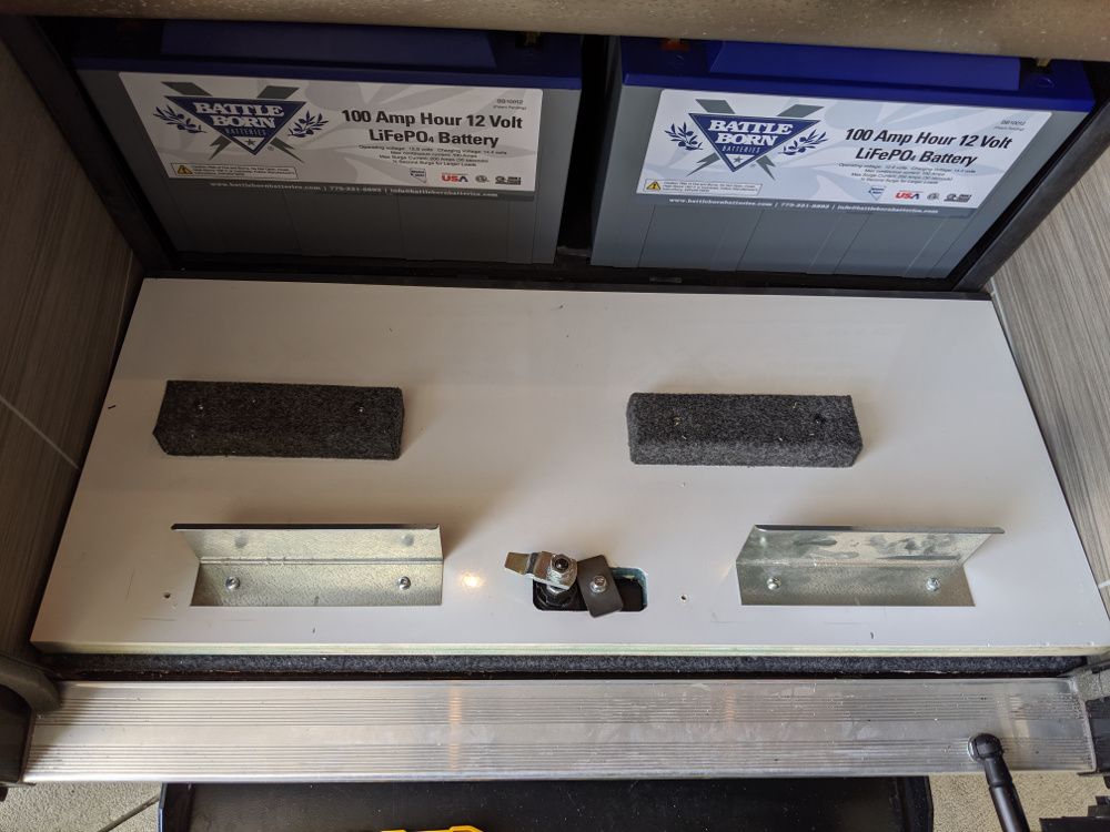
So basically I installed one in the rear and both sides and although its quite rigid now with the top bar I will put a little foam spacer between the batteries and the front metal just in case the top bar should rattle loose someday.
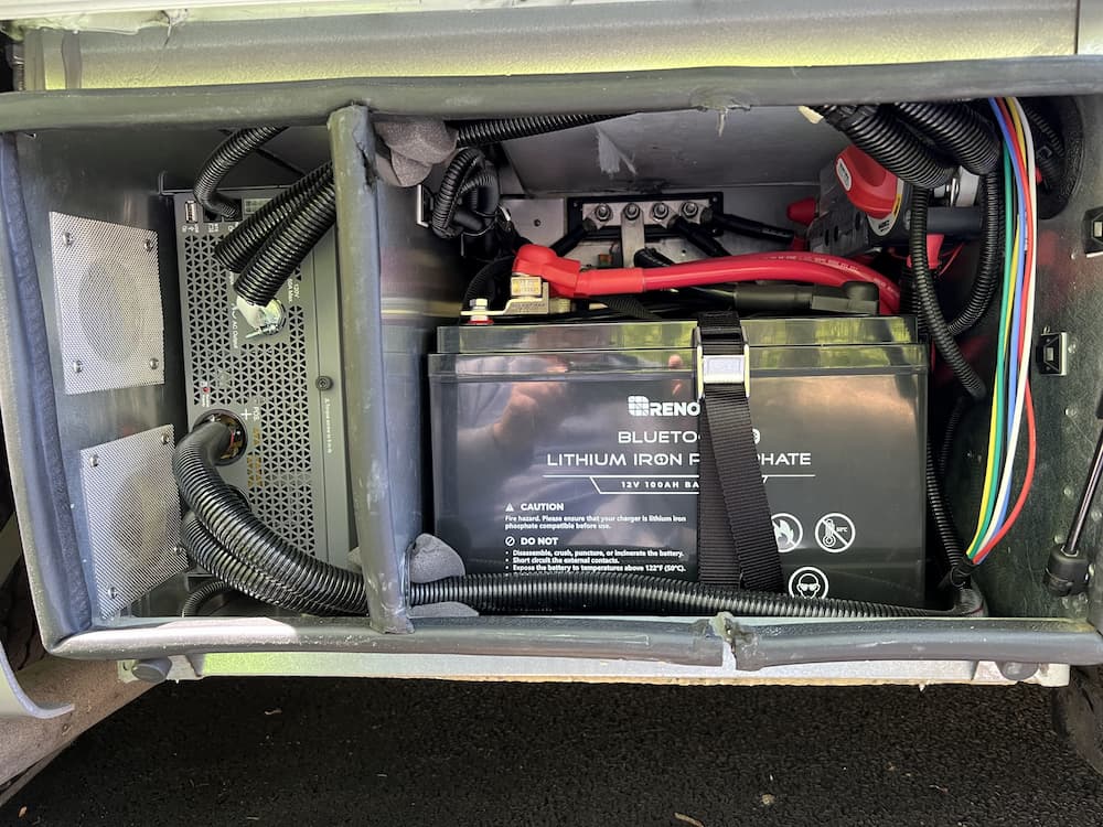
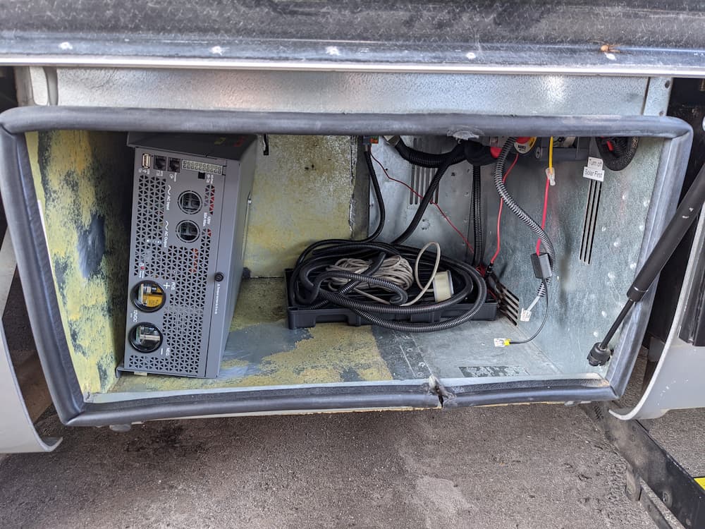
This is the final picture powered up and running. The mount is tough enough to take the jostling that we sometimes encounter on back roads out west leading to remote camping spots.
Note that my inverter was moved to the left side (long story) so I installed the batteries in this orientation. This way the bms (which is now on the right side of the battery in picture above) is right next to an air vent for cooling and away from the inverter. For a standard Unity with the inverter on the right side the batteries would usually be flipped around with the Epoch logo showing on the front.
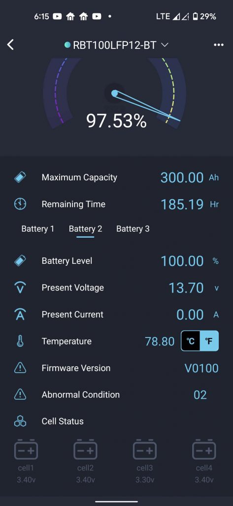
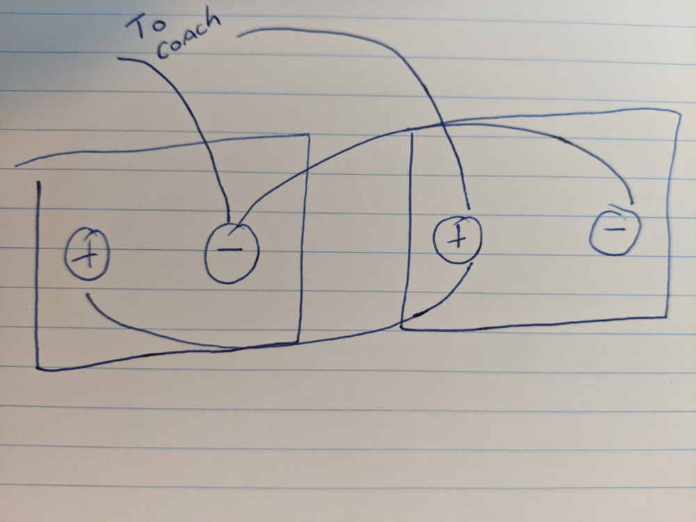
When connecting, I first checked to make sure both batteries were very close in voltage, with less than .05 volts difference. Then I connected the positives first (both batteries) and finally the negatives after making sure my Marinco master switch is off. There is just enough room inside to (barely) connect the negatives, and fire up the app and with satisfaction watch the battery that had a tiny more charge drain off to its neighbor.
And lastly turn the Marinco switch to on. Wait a few seconds. This is to allow the battery to fully boot and stabilize. (Not really needed in this scenario, because the Epoch BMS seems to be always on and my Xantrex inverter does not have a huge inrush current like the Victron does, but good practice anyway). Then to “Parallel” to connect the inverter.
The Epoch bluetooth app is pretty good and includes the ability to turn the MOSFET (internal transistor switches) on and off – both charge and discharge. Since the battery uses an off the shelf “JIABAIDA BMS model jbd-sp04s060” there are probably a dozen apps you can use. I’ve tried a few. Some allow you to save the (dozens) of bms settings.
Which leads to the only thing I hate about the battery. There is no provision for a Bluetooth password. Because of that, a camping neighbor could, through mistake or willfully, turn your batteries off, or even worse, change an internal bms setting and fry them. (The Epoch app does not allow this, so most campers woudn’t have that ability).
This is all extremely unlikely obviously, but still, in the world we live in today, it would have been better if Epoch had setup the Bluetooth dongle to enable a password, or only allow pairing when a switch was pressed or something.
The Epoch BMS is very standard. I setup all my chargers for a 14.2 volts absorption, a 13.5 volts float, and a 30 minute fixed absorption time with zero tail current. I let the Xantrex top them off, and everything looks to be working great so far.
March 2025 Update:
Batteries working as expected. I happened to visit their website one day and now they sell these gems: Would have saved me an hour or two’s work buying, cutting, and installing sheet metal brackets, so this would be the way I would go if installing now!
October 2025 Update
After my Xantrex failed on the road I had to remove the batteries to service it. The battery mounted terminal fuses became a real pain! I don’t have much clearance, and they were a friction point getting everything torqued down easily and safely. Thanks to a conversation with another LTVer, I became aware that they also make a dual terminal fuse. The beauty of this is I could just hang it off the Class T fuse, eliminate a bus bar, and make it much easier to slide batteries in an out.
So in the picture above you can see the fuse bar hangs directly on the Class T fuse, and gives each battery a 250 amp fuse – but moved the fuses off the battery for simplification. Before I mounted the red safety cap it looked like this:
Some of the stuff I used, besides the batteries themselves:
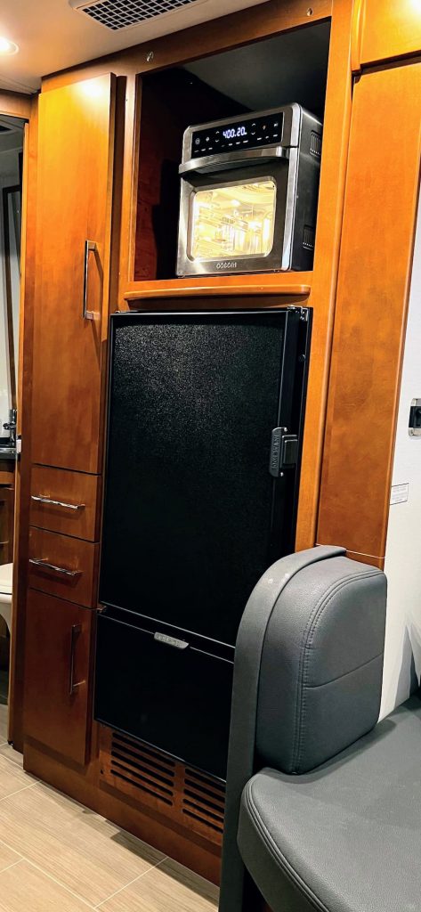
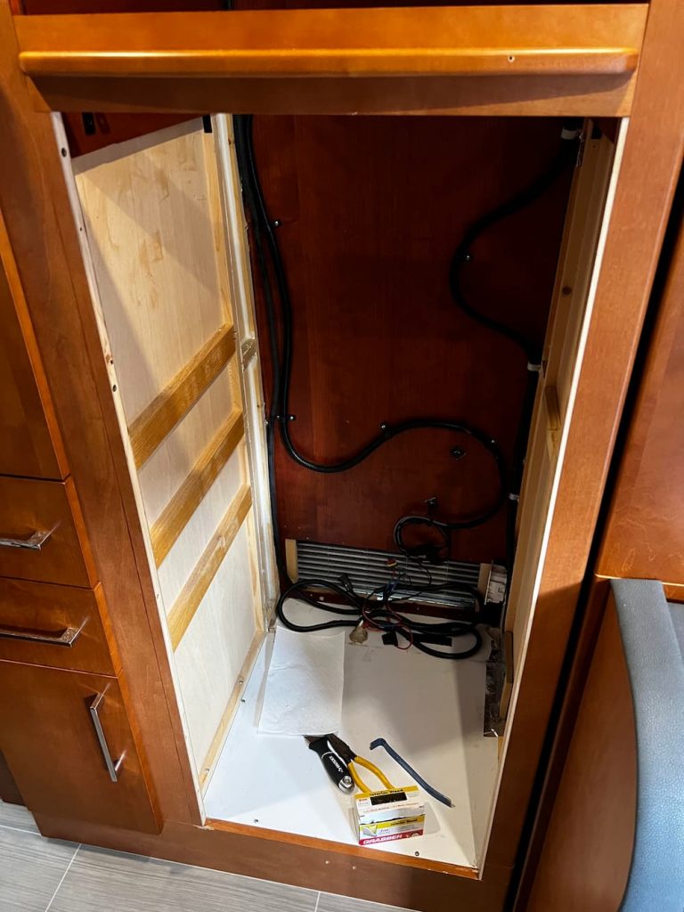
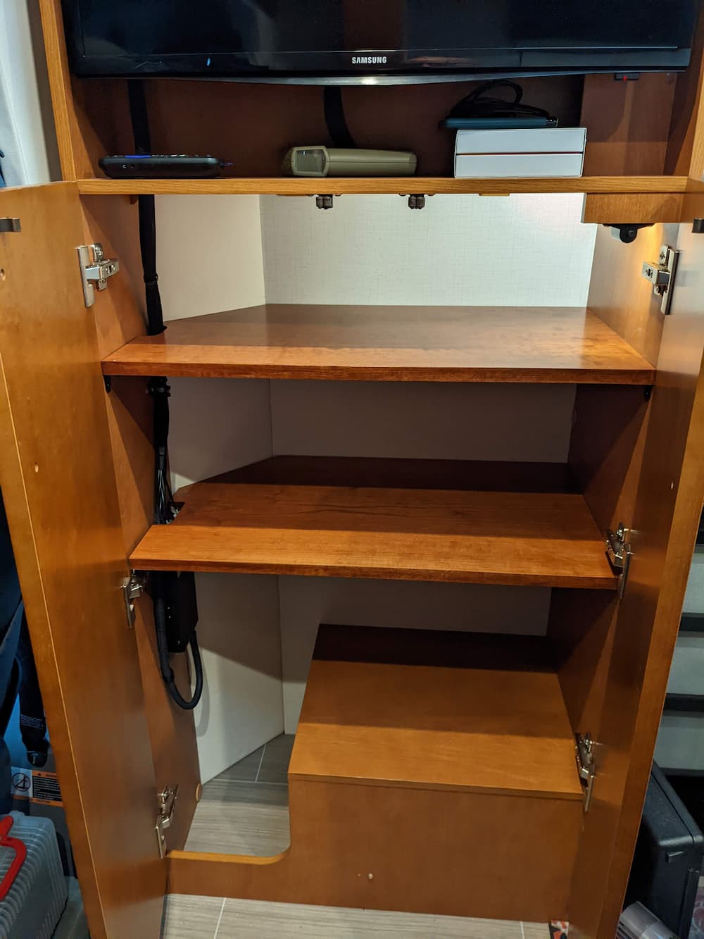
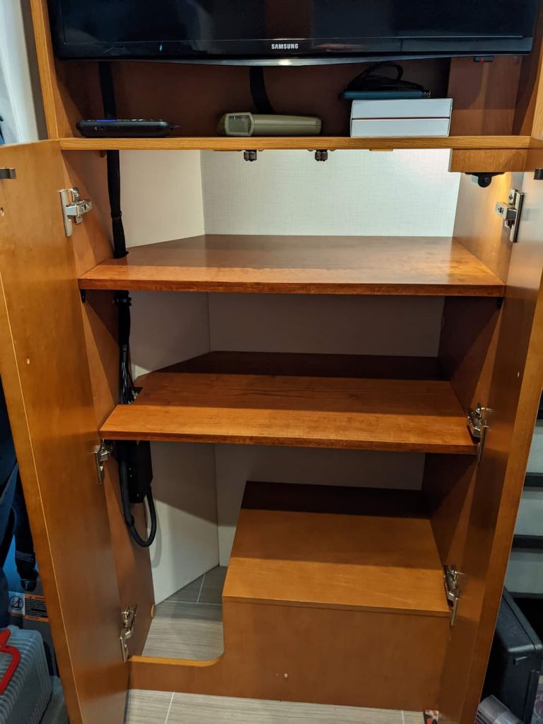
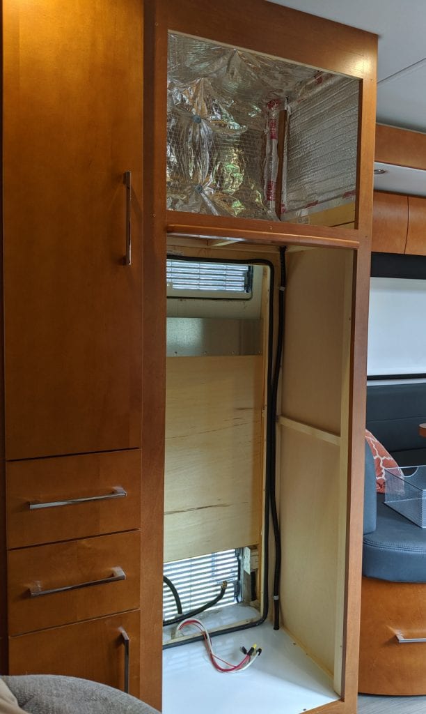
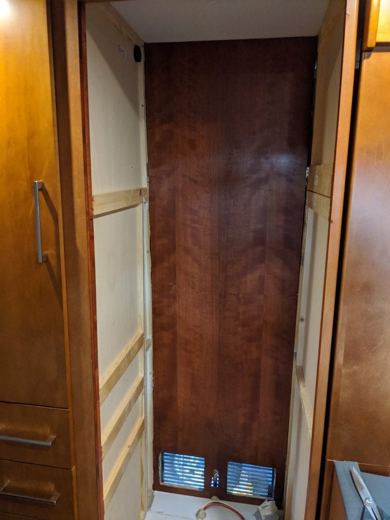
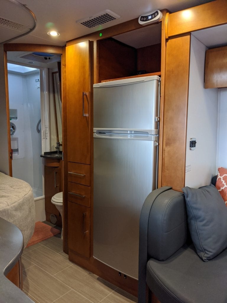
I previously installed a NovaKool Dual Compressor Refrigerator, and I took that opportunity to gut my original refrigerator cabinet and reshape to my liking.
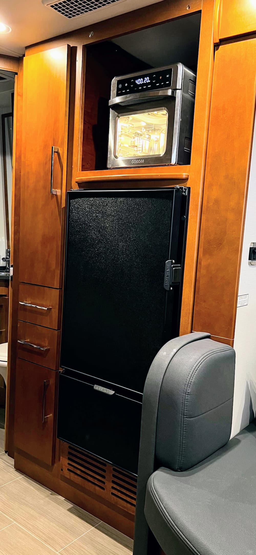
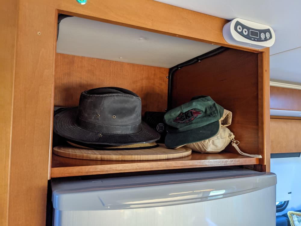
One thing I never used much was the OEM Microwave oven. I know some people like it, and it can bake also, but we rarely if ever turned it on. We have found after camping over a few years what we really miss is a toaster oven and an air fryer. So I “skinned” the area over the refrigerator in matching cherry plywood to be able to install the appliance of my choice. Leaving the area open also allows the hot air to dissipate easier, and there is a small gap at the rear of the shelf to also help vent the heat from the fridge.
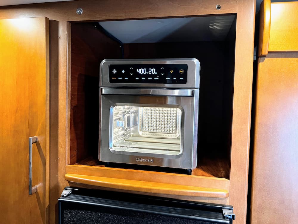
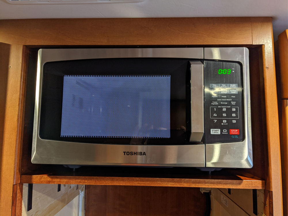
We ended up buying this diminutive guy:
It looks huge in the picture but is quite small (and inexpensive). But it does just about everything even has a rotating rotisserie and a rotating basket for things like air fried french fries. And of course it toasts as well:
We tried it out at home and especially like the rotating basket which makes french fries come out so much better.
For us this makes a lot more sense than a Microwave combo. And the tremendous heat an air fryer expels is best absorbed on an open shelf. So here it is:
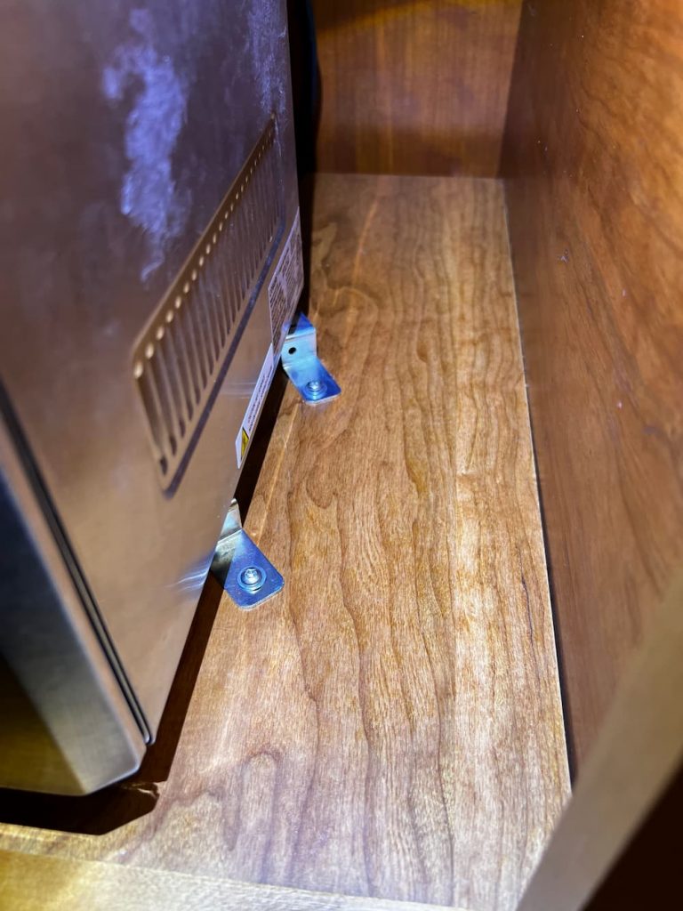
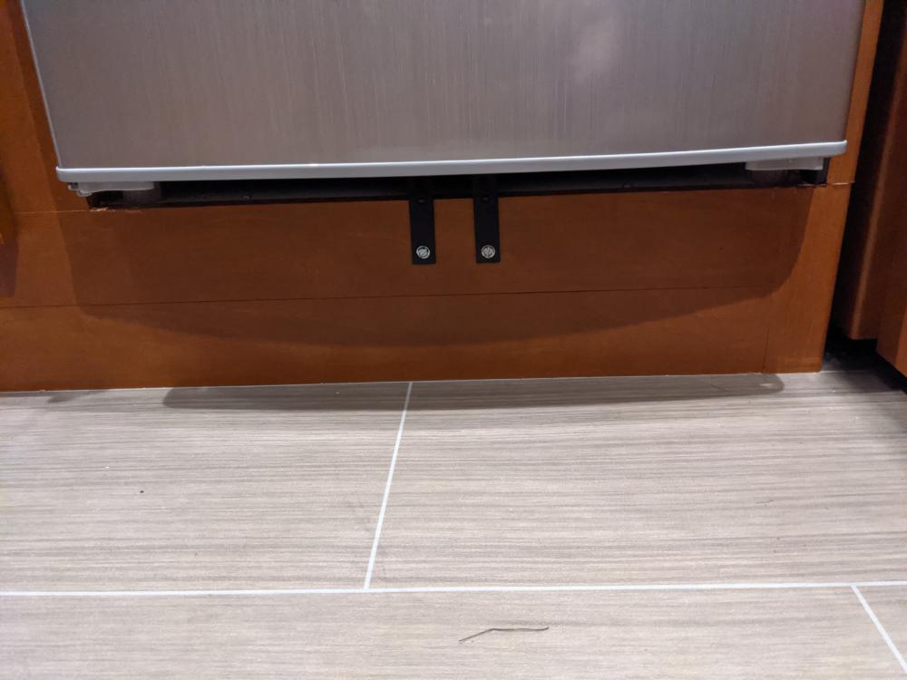
I am going to need something to hold this thing down, so I ordered some small Z-brackets off Amazon. I’ll post more when they arrive and its safely screwed down, but so far this little thing seems perfect for our small RV kitchen.
MARCH 2025 –
Still love this thing! I used the Z brackets to screw down (needed a few washers) like this. When cooking with the air fryer it gets incredibly hot but most heat seems to expel out the front. I watch it carefully as its still new but it seems the area around it isn’t at risk.
Still, nothing is perfect. Its large and heavy, and I really got tired of lugging it around at every stop in the wilderness. On one or two occasions we even deployed it at rest stops to navigate, and that gets old fast.
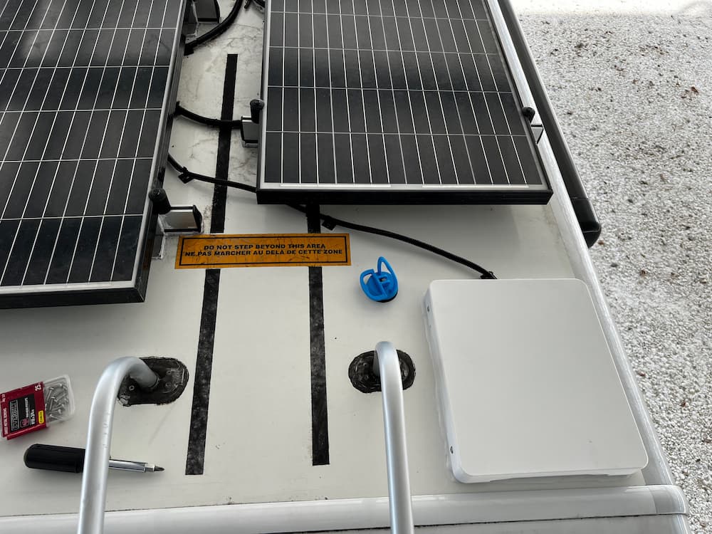
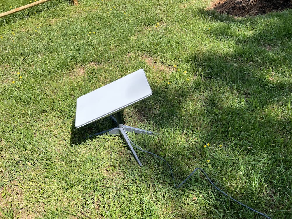
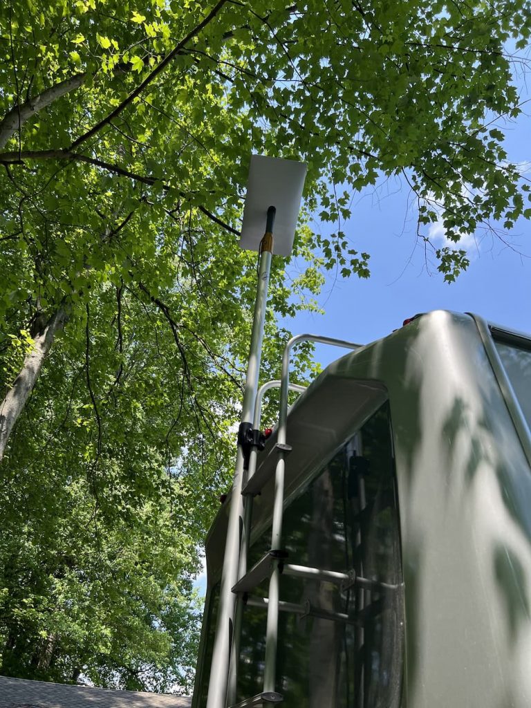
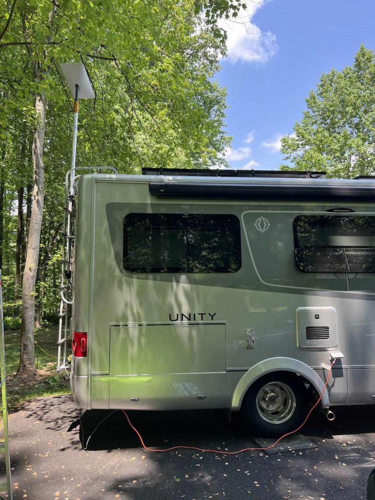
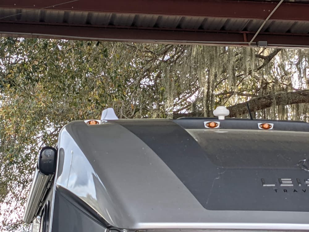
The mini is more to my liking. It runs on DC out of the box, is tiny and uses way less power. Its small enough that I have room to roof mount it and eliminate the PIA factor.
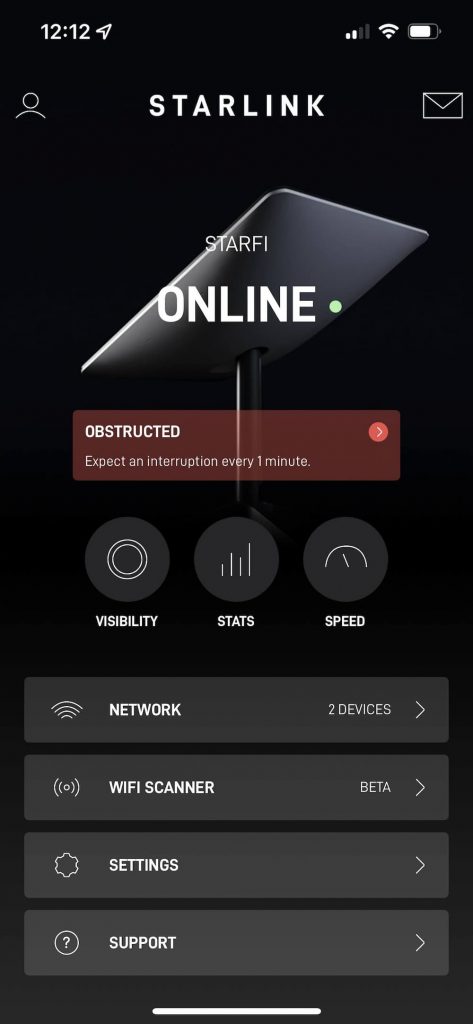
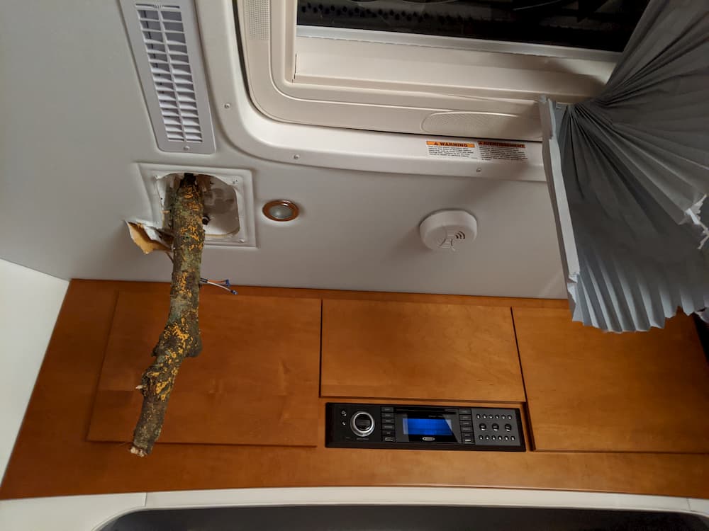
But – I wanted the ability to also dismount it in a pinch. Let’s say I stay somewhere for several days under the trees – I am going to want to try moving the Starlink mini around, to maximize my signal.
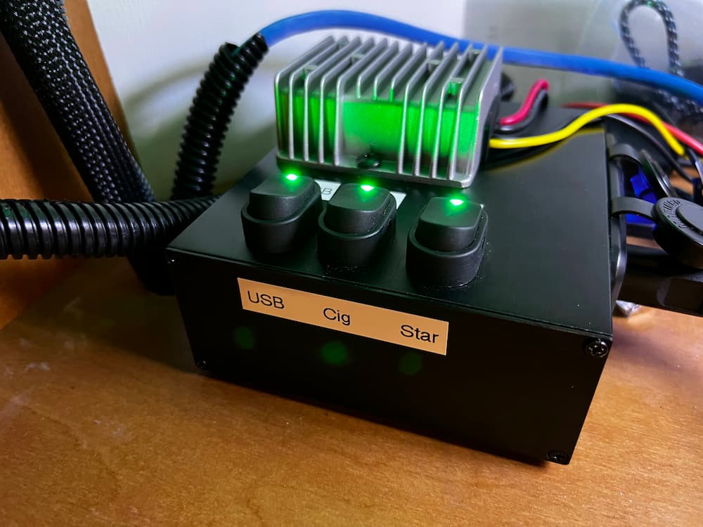
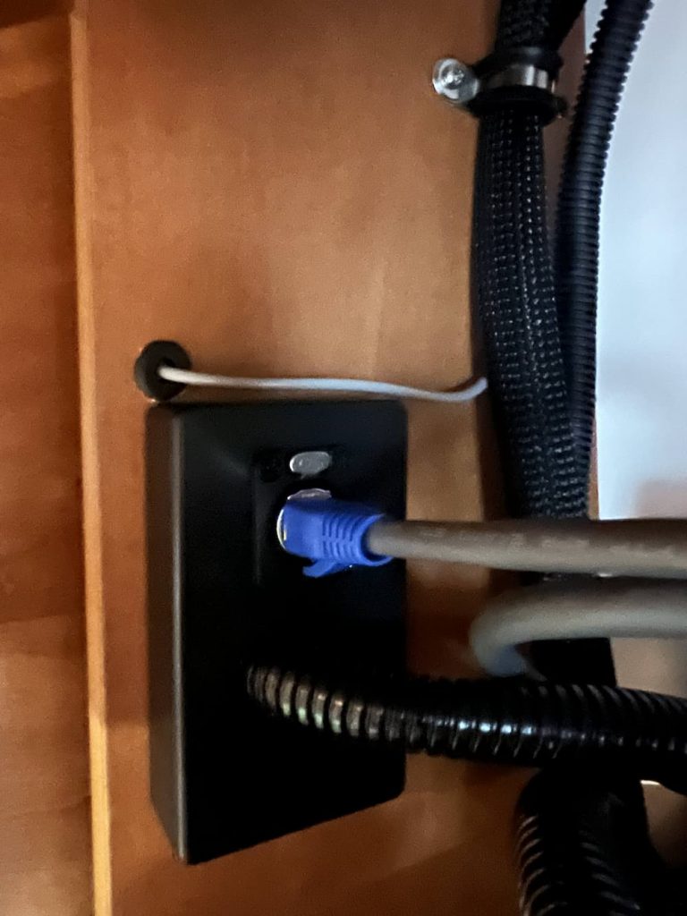
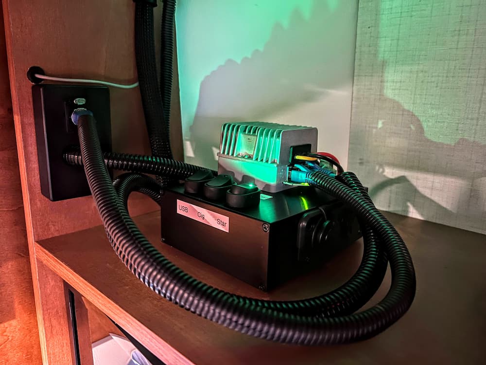
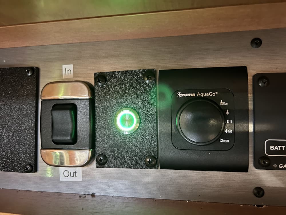
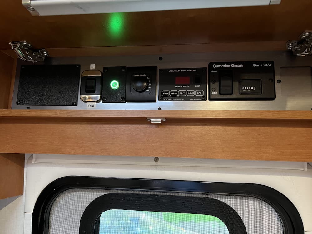
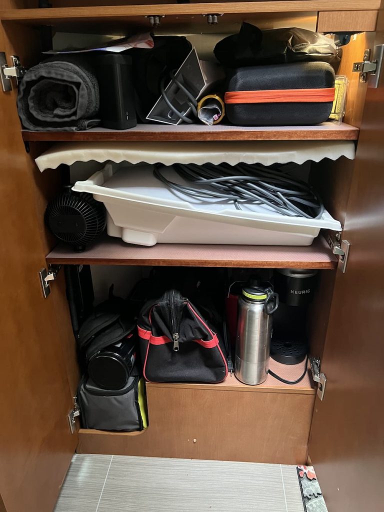
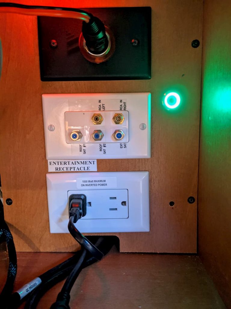
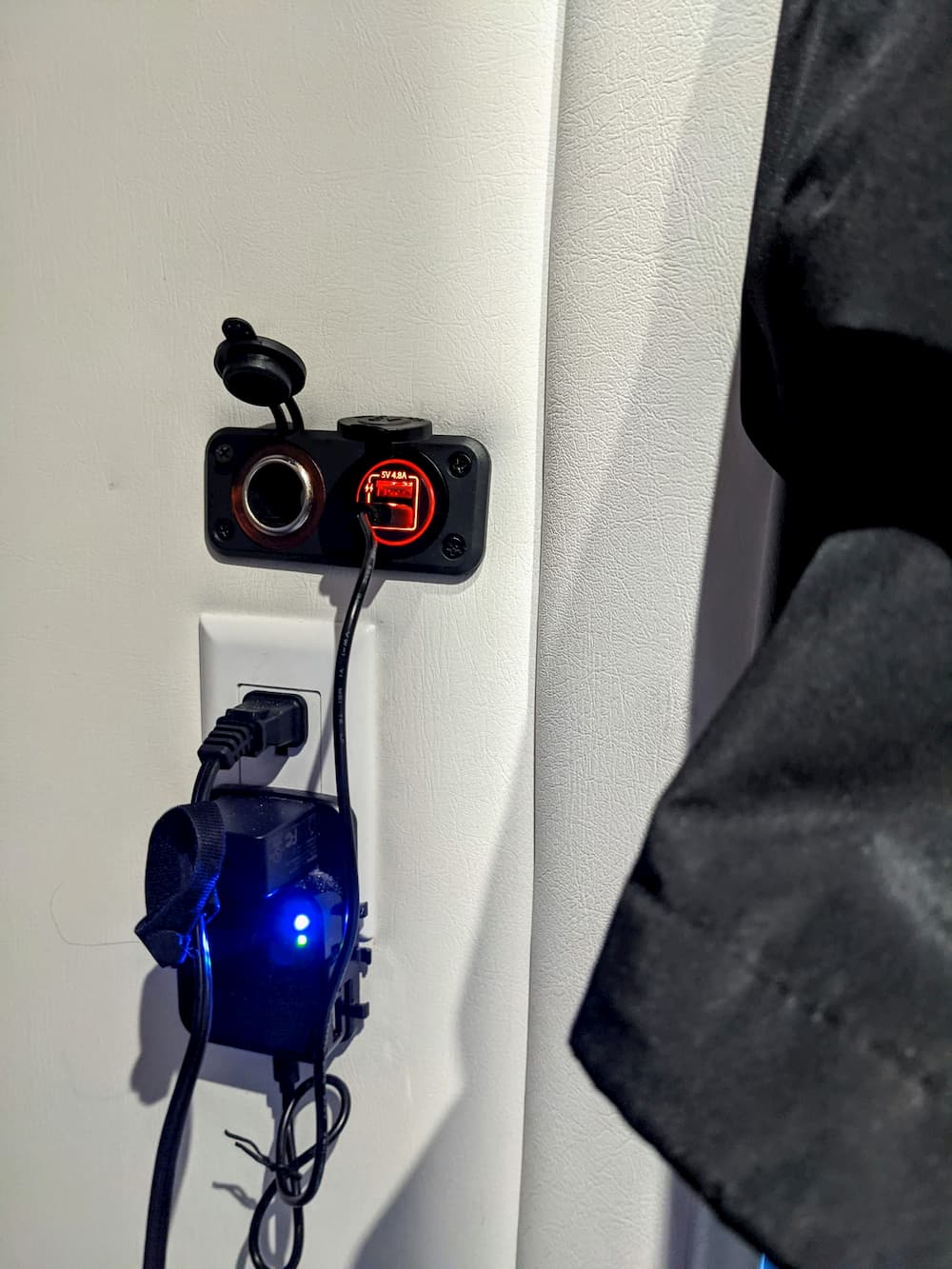
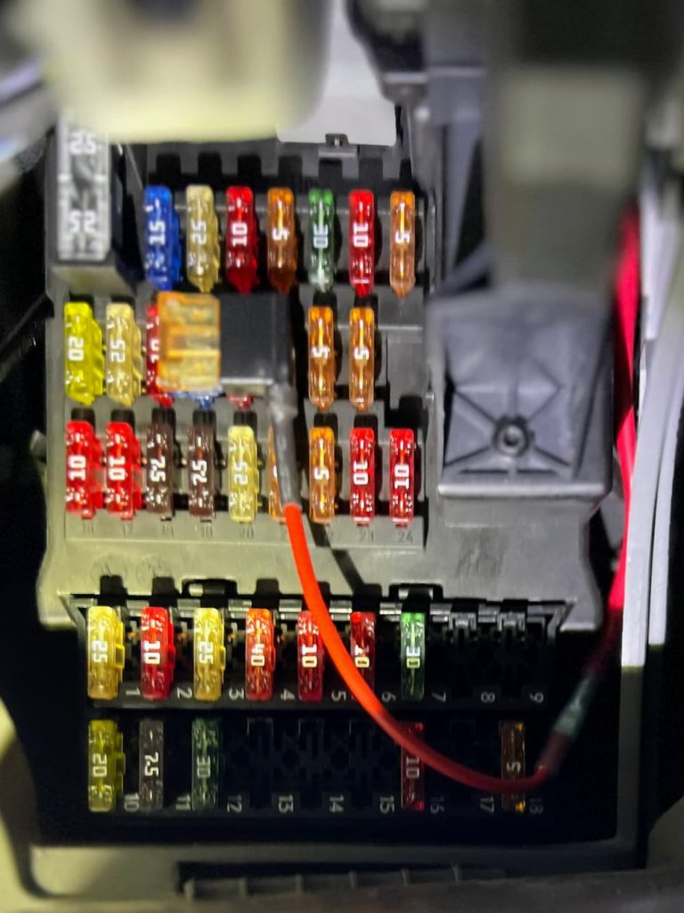
Luckily, my RV came with a dated junky thing called the Winegard 2, which is an old school WiFi collector and cellular modem with. really bad interface and a limited use case. So when I removed that from my roof years ago I preserved the small 12 volts wires for it. These terminate inside my entertainment center cabinet with a 3 amp fuse.
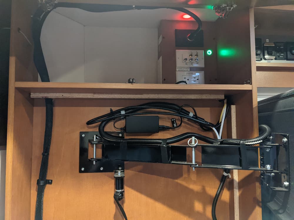
So perfect! Mini seems to like a higher voltage, and thats a long run of wire, so I added a 12 volt to 36 volt buck converter.
I mounted this on a metal box but it also would have fit inside the wire cabinet. I happened to have this box already mounted for the old Starlink so it was just a swap.
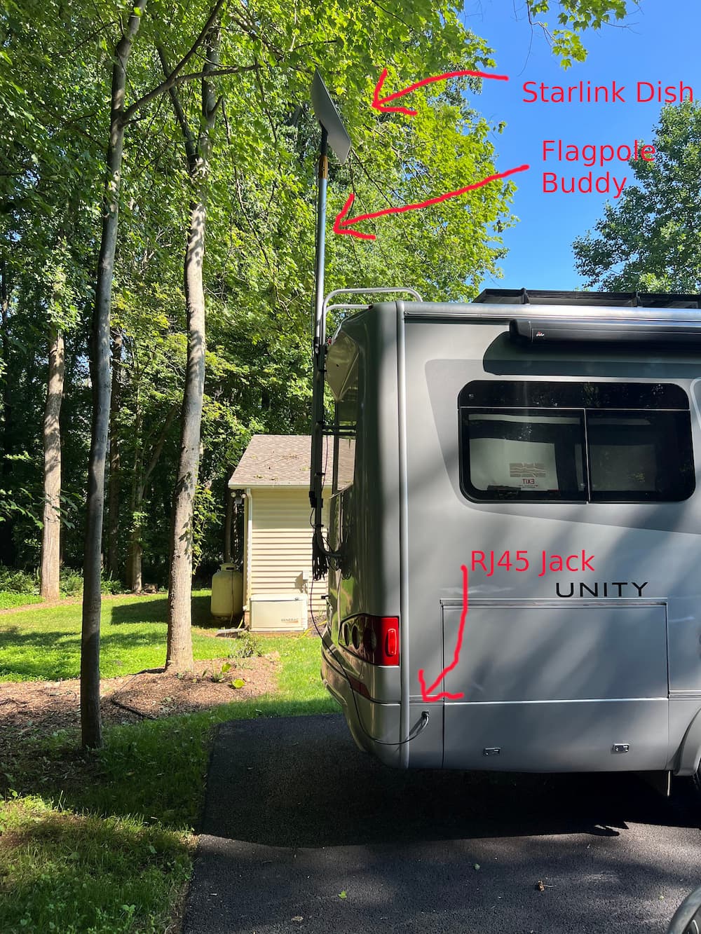
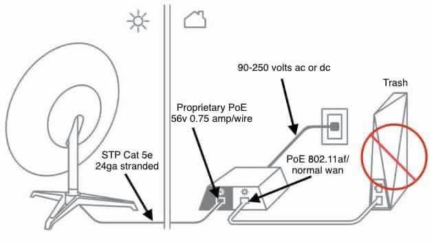
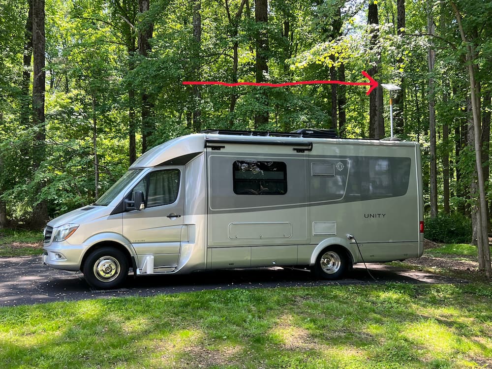
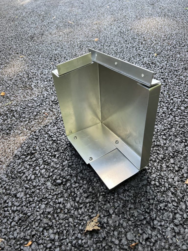
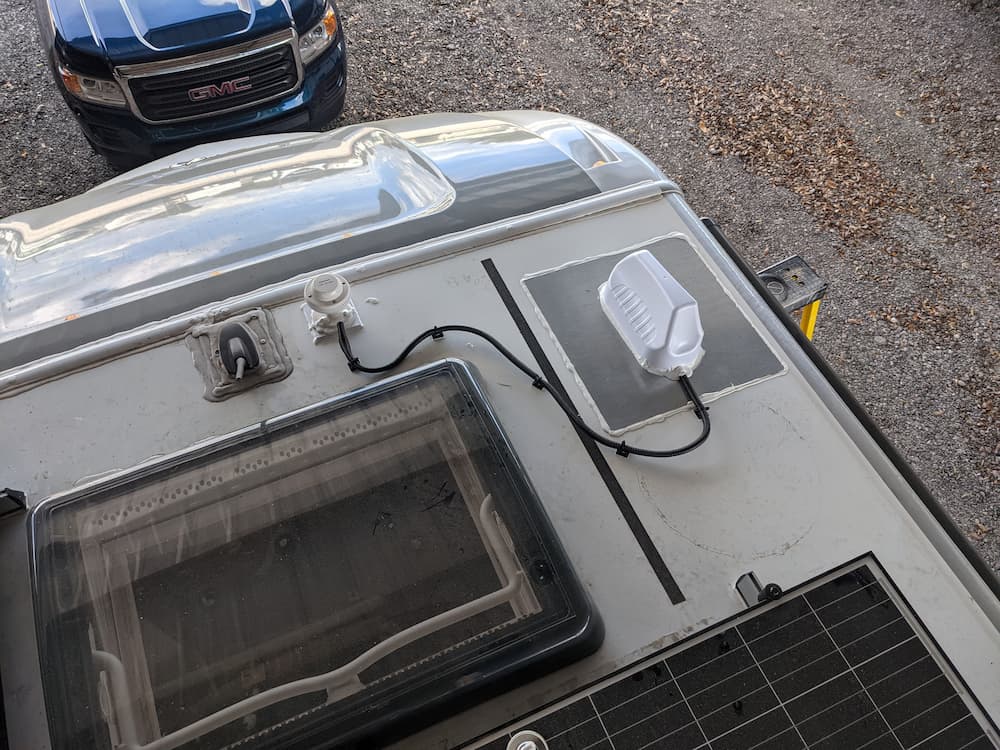
After that, it was just a question of attaching the mount to the roof. The one I bought off Etsy is unique in that the Starlink is fully enclosed and its (somewhat) easy to remove the Starlink if necessary.
One problem I faced is that my entire roof is full of obstructions. It didn’t seem to matter much in testing, and I eventually decided to put it right next to my ladder. One advantage here is that my roof is crowded and I can reach it even without stepping on the roof. The nearby obstructions and the ladder didn’t seem to matter in testing, but time will tell.
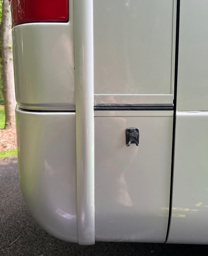
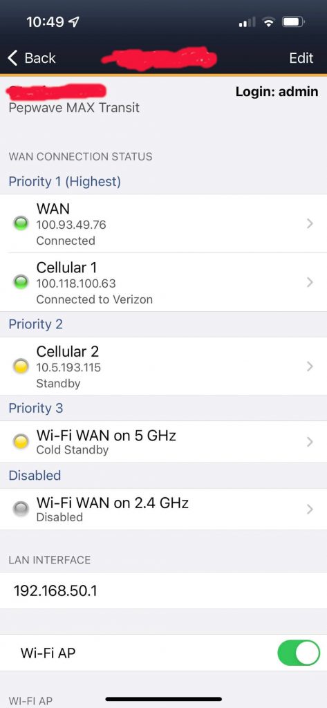
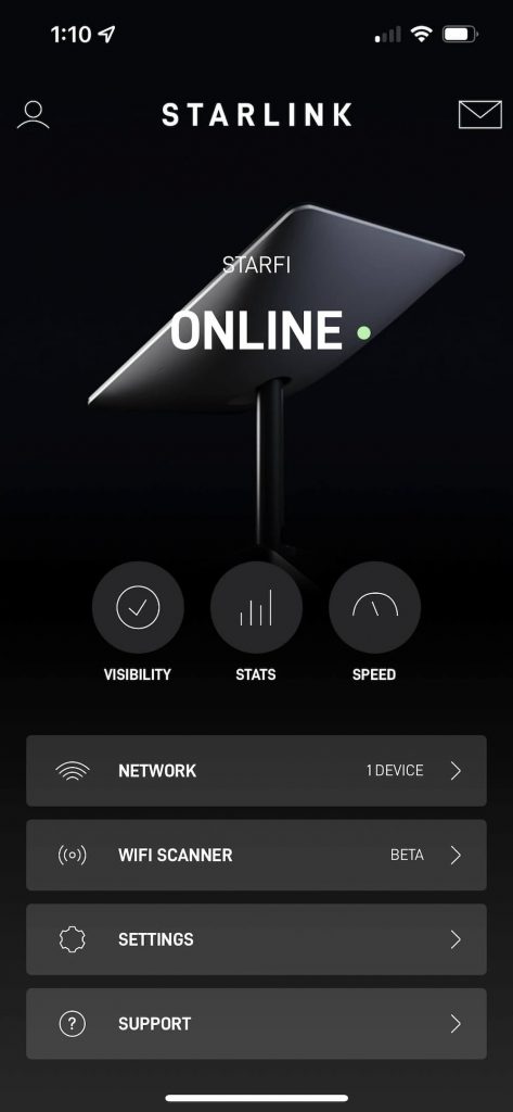
And a consideration for me is that I prefer to route my Starlink through my Pepwave Router. I would prefer to connect by RJ45. But that would take more time and I’d have to dig under my cellular antenna to get to the hole I drilled through my roof. So for now I will just connect to the Pepwave over Wifi. I probably won’t notice the speed difference. Connecting through my Pepwave makes it easier for everything in the RV to have a permanent connection. For example traveling on the east coast I don’t usually bother to turn on Starlink and keep it paused.
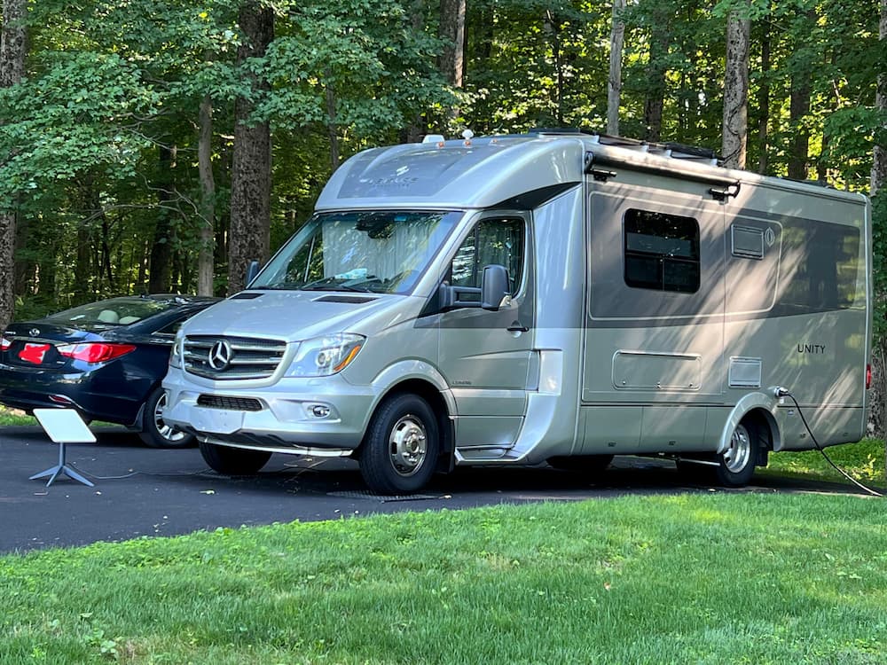
Here is the final result. I put 3M tape on the bottom and drizzled the perimeter with Dicor.
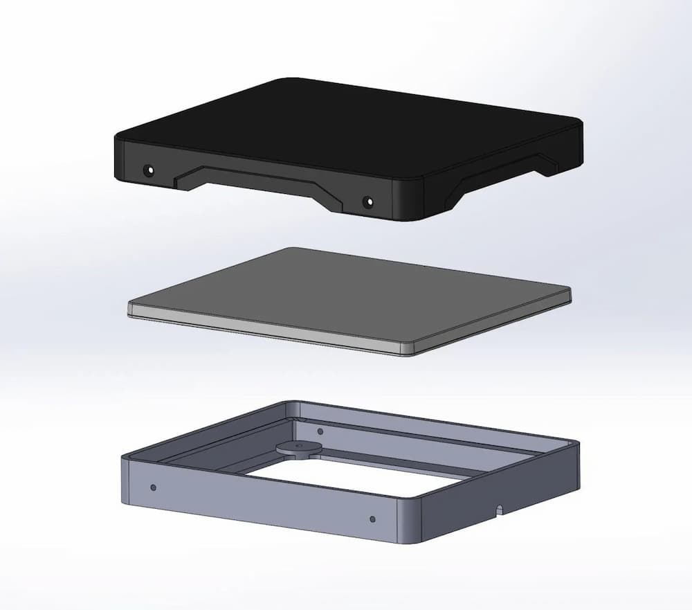
The Etsy mount is near perfect. It protects the Starlink from the elements and holds it securely. The cover is held down with 4 screws. The box is so tight that I needed suction cups (see below) to remove the Starlink from it easily. This is what the mount looks like:
I chose mine in white. In the diagram above you tape/glue only the bottom mount to your roof. The middle component is your Starlink Mini, and the top is the cover. So the mini is easily removable with 4 screws. The Etsy product link.
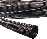
These are the rest of the products I used for the job, besides the Starlink itself. The short Starlink DC cable below was cut in half and connected to the Winegard wires on the roof. The UV wire loom protects the wires from the sun.
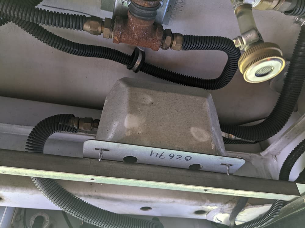
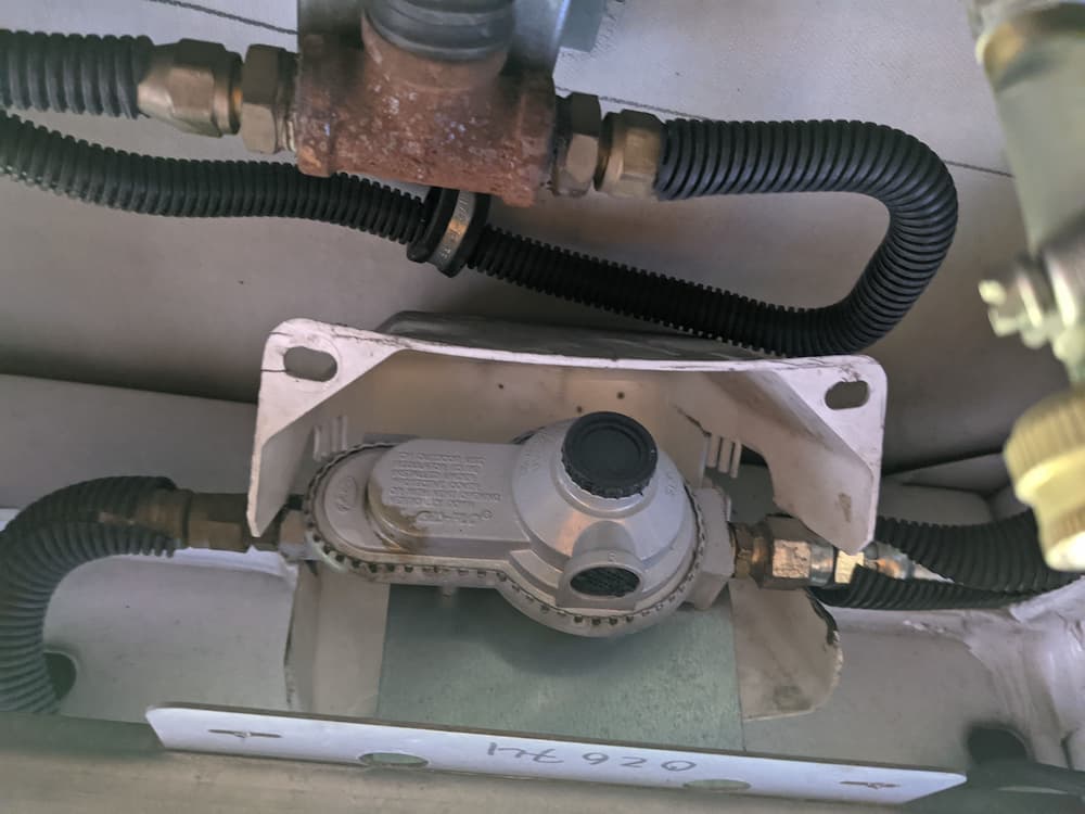
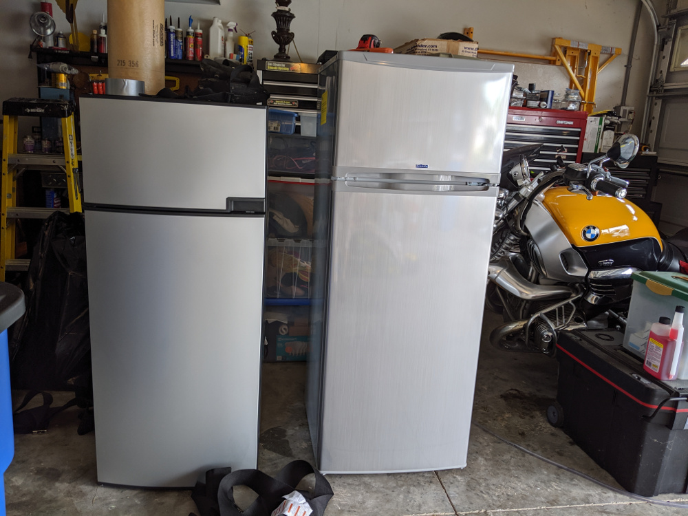
I previously installed an Isotherm Cruise 219 refrigerator. This gigantic refrigerator was a huge pain to install because it required extensive cabinet modifications.
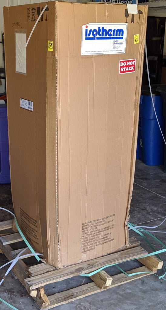
And after a couple glitches I have been reasonably happy with it. I probably would have continued using it for years, until this NovaKool RFU6406 D fell from the sky into my hands. Literally.
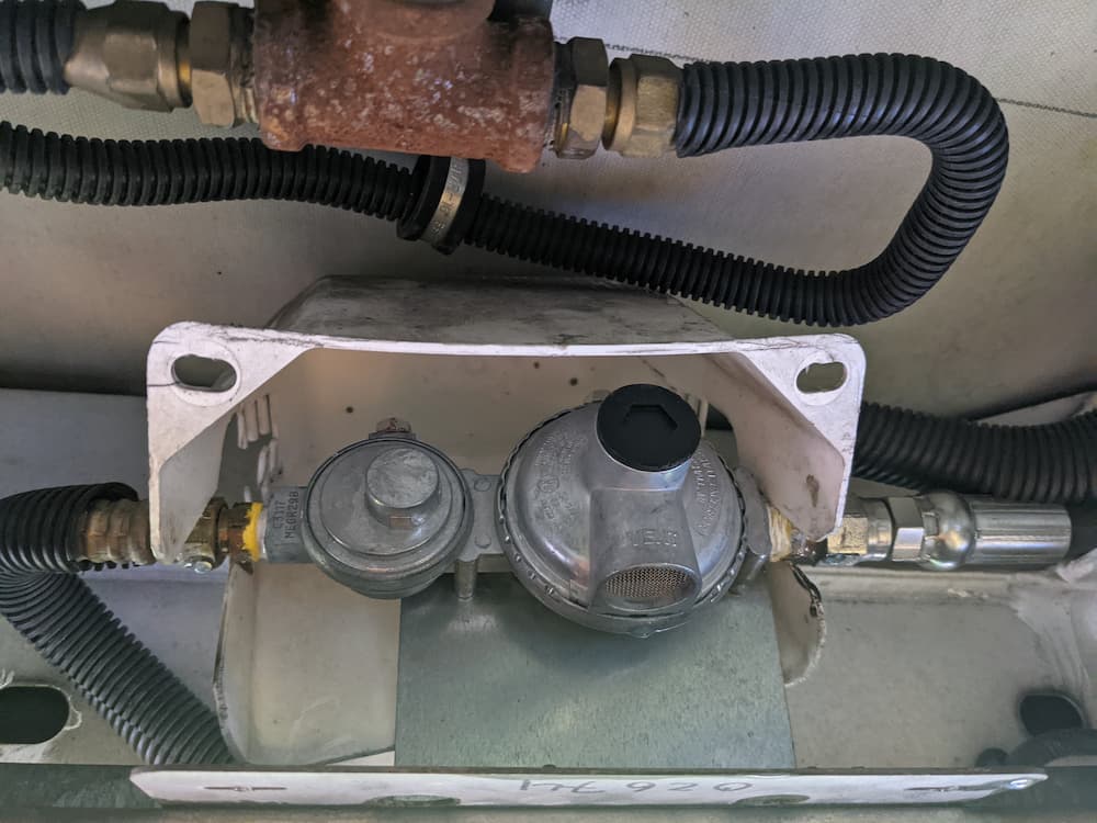
This is the base of the refrigerator. It looks like Fedex dropped it. There were other superficial signs of crushing, so its also possible they stacked them or something. There was no damage to the parts of the refrigerator that you can see when installed, except for the front metal bottom grill which is replaceable.
Anyway, it was delivered to a customer who naturally demanded a replacement. After a claim was filed and approved, the customer received a new one. When he asked NovaKool what to do with the damaged one they replied that he could discard it.
And he did. Right into my greedy hands lol! I was thinking it might be possible to repair it.
At first glance you might wonder why I would even want this refrigerator. Its specs look far less impressive than my Isotherm. Its much smaller for example, more like the Dometic fridge that came with my RV.
But it has one killer feature – dual compressors.
Home refrigerators typically have a temperature setting for both the freezer and the refrigerator so each can be maintained at a safe comfortable zone. They may achieve this with separate compressors or a single compressor with zone valves but the effect is the same.
In contrast almost all RVs have a single temperature control. To achieve this the fridge diverts a set amount of cooling to the freezer and hopes for the best.
Most of the time this is fine at 75 degrees.
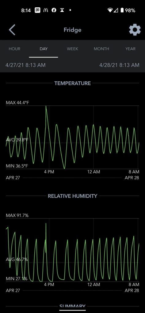
In extreme temperatures however the refrigerator and freezer diverge from the average conditions they were designed for. So I found that in extremely hot weather the refrigerator struggled to keep up, while the freezer wastefully got far colder than needed – sometimes as low as 10 or 15 below zero.
Conversely, in extremely cold weather the refrigerator stayed off for a long time and the freezer drifted much to warm, rising to as high as 20 degrees.
So I found my self often fiddling with the thermostat and trying to find a compromise. It was not a huge deal and I could have lived with it, but the idea of having a more powerful refrigerator and 2 independent zones was very appealing.
The NovaKool is really a completely separate fridge stacked on top of a freezer. In fact if the fridge failed you could set the freezer warmer and at least use that on the way home. Each compressor is about 75 or 80% as powerful as my single compressor Isotherm, so the fridge and freezer should have far more cooling capacity.
So I didn’t need a new fridge but this was too good an offer to turn down!
The first step was seeing if it was even salvageable. I can replace anything electrical but finding a Secop refrigeration engineer is almost impossible, and if I could find one, they charge more than brain surgeons.
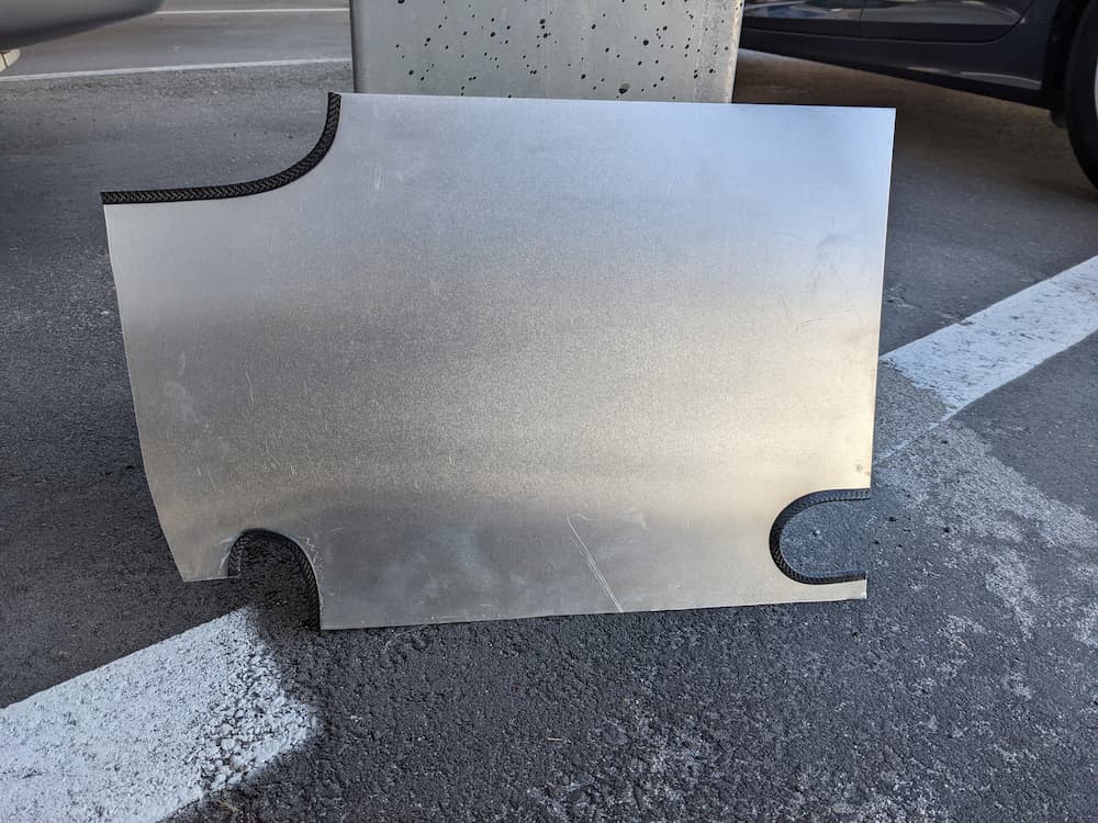
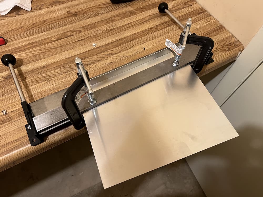
So I ordered these 2 heavy steel plates cut to size, and 4 super long threaded rods. I then drilled 4 holes through the edges, and slowly tightened the homemade jig.
It made a lot of strange noises and popping sounds but it worked!
For good measure, I installed a “foot” on the worst crushed part to retain the new shape.
All this seemed to work, and while its not exactly perfectly straight, it moved the copper lines and compressors, etc. closer back to where they are supposed to be.
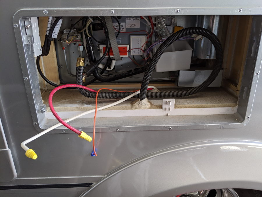
Next, I had to hook up 12 volts for testing as this fridge lacks any AC input.
And… it worked! Sort of.
Nothing exploded or leaked, and everything got cold. But the fridge cooled disappointingly slow compared to my Isotherm. Something didn’t seem right. I looked at the wiring and it turns out NovaKool installs “speed resistors” on these to derate the refrigerator and freezer to lower speeds.
Why? Why? Why? You might ask. Well, the answer is in numerous documents they publish on the subject. They slow down the compressors because they are most efficient when running almost continuously. You save a little energy and the fridge runs quieter.
Except, and its a big one – not only will the fridge take much longer to cool down, every time you open it you will experience the same slow cooling. The NovaKool solution works best if you never open the fridge and don’t care that the initial cool down takes 24 hours.
Which is all nonsense, as anybody who owns an RV knows. I have 400 amp hours of lithium so I’d much rather waste a few of those amps and have cold food.
So the first thing to do is speed up the compressors. You can easily do this by changing the speed resistors readily available from NovaKool. But fortunately, I have already hacked the Secop compressors and was able to remove the speed resistors and reprogram both compressors to run all out.
Which I did, and restarted the fridge. This time fridge and freezer cooled much faster, but there was one more problem – both were randomly turning off at times which made the cooling slower.
At first I thought there were damaged components overheating, but there were no compressor fault codes on my equipment. So I tried an experiment of “hot-wiring” freezer and compressor to run continuously for now.
And… man did that sucker fly! In 2 hours both compartments were fully cooled down – fridge under 39 and freezer near zero.
So its a bit of a mystery to me why the factory thermostats seem not to work well. There doesn’t appear to be any damage. Coincidentally, I had already built an electronic thermostat for the Secop compressor in my Isotherm, and it was pretty easy to modify it for dual compressors. My electronic control features an Internet monitoring and settings app, so why not use that instead of troubleshooting the crude mechanical thermostats.
In fact the electronic thermostat worked so well that I designed a custom PCB board for the dual processors to make it a little tidier.
I ran the salvaged fridge for a week in my garage and couldn’t find anything wrong with it, so its finally time for the installation!
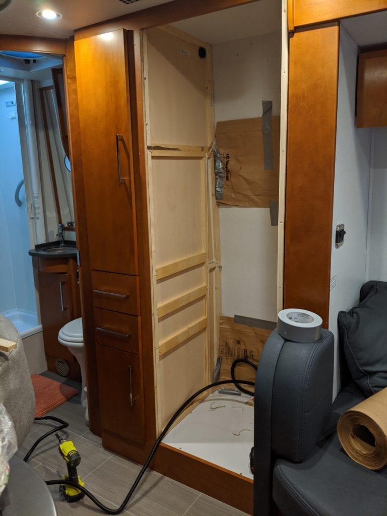
The actual install was just a lot of cabinet work for me making mine smaller. There is no propane, no AC, and not even a water drain, making this just about one of the easiest fridges to install, once I got past the extensive woodwork.
I installed a 3/8″ filler strip on the left side of the cabinet. I also had to move the shelf and the vertical filler to accommodate the NovaKool. This is what the cabinet looked like now right before I slid the NovaKool in: (Actually it did not fit and I removed the 1/4″ filler strip on the right and it then fit perfectly)
I plan on someday installing a standard kitchen toaster oven / air fryer above the refrigerator, so I put cherry 1/4″ stained cherry plywood on the sides above and a 3/4″ cherry plywood shelf down. I never liked the idea of the enclosed microwave oven – seems like an overheating hazard to me. This way I can put whatever I like on top – a combo toaster oven / air fryer is appealing.
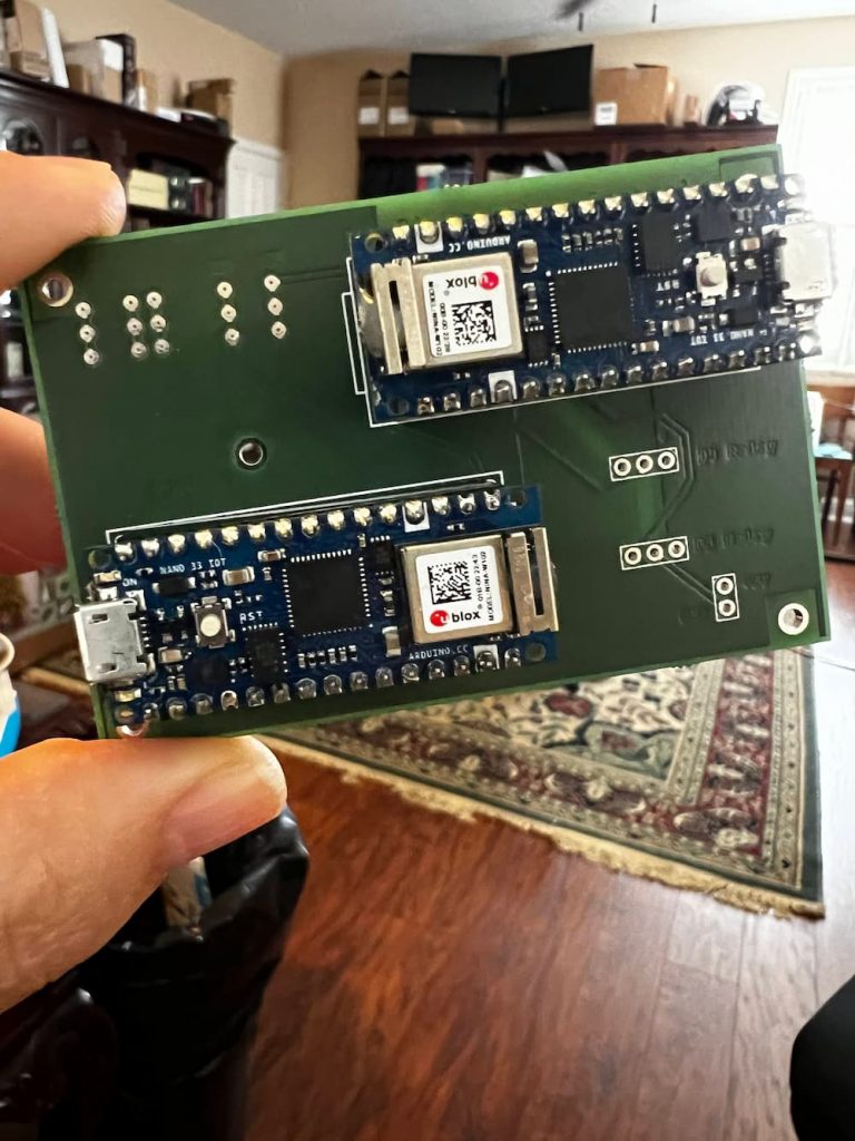
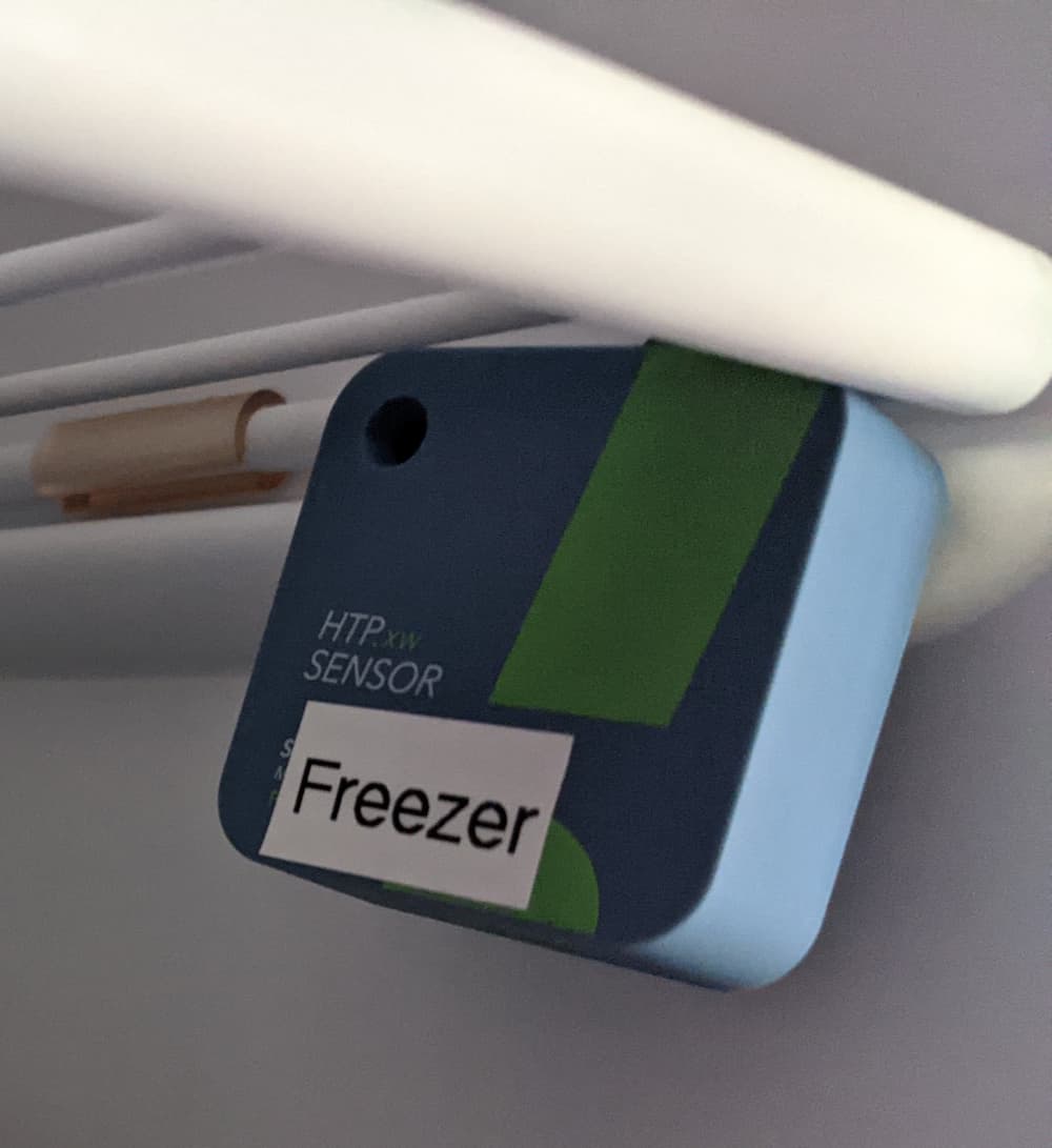
This is the thermostat I eventually built. It has 2 Arduino Nano 33 IOT microprocessors. One of them polls the SensorPush Bluetooth Sensors and turns the refrigerator on and off as needed using 5 volt relays. The other microprocessor board acts as the IOT relay and manages a control panel accessible on the Internet.
As a bonus, the temperature and setting are available on an app and work over the Internet!
The advantage of an electronic thermostat is precise temperature adjustments, Internet monitoring and a settable “Hysteresis”. Hysteresis lets you decide what range the temperature will be, for instance I typically set the refrigerator to turn on at 39 degrees and turn off 35 degrees. The 4 degrees of hysteresis helps with humidity and frost control – also you don’t want the compressor turning on and off more than necessary.
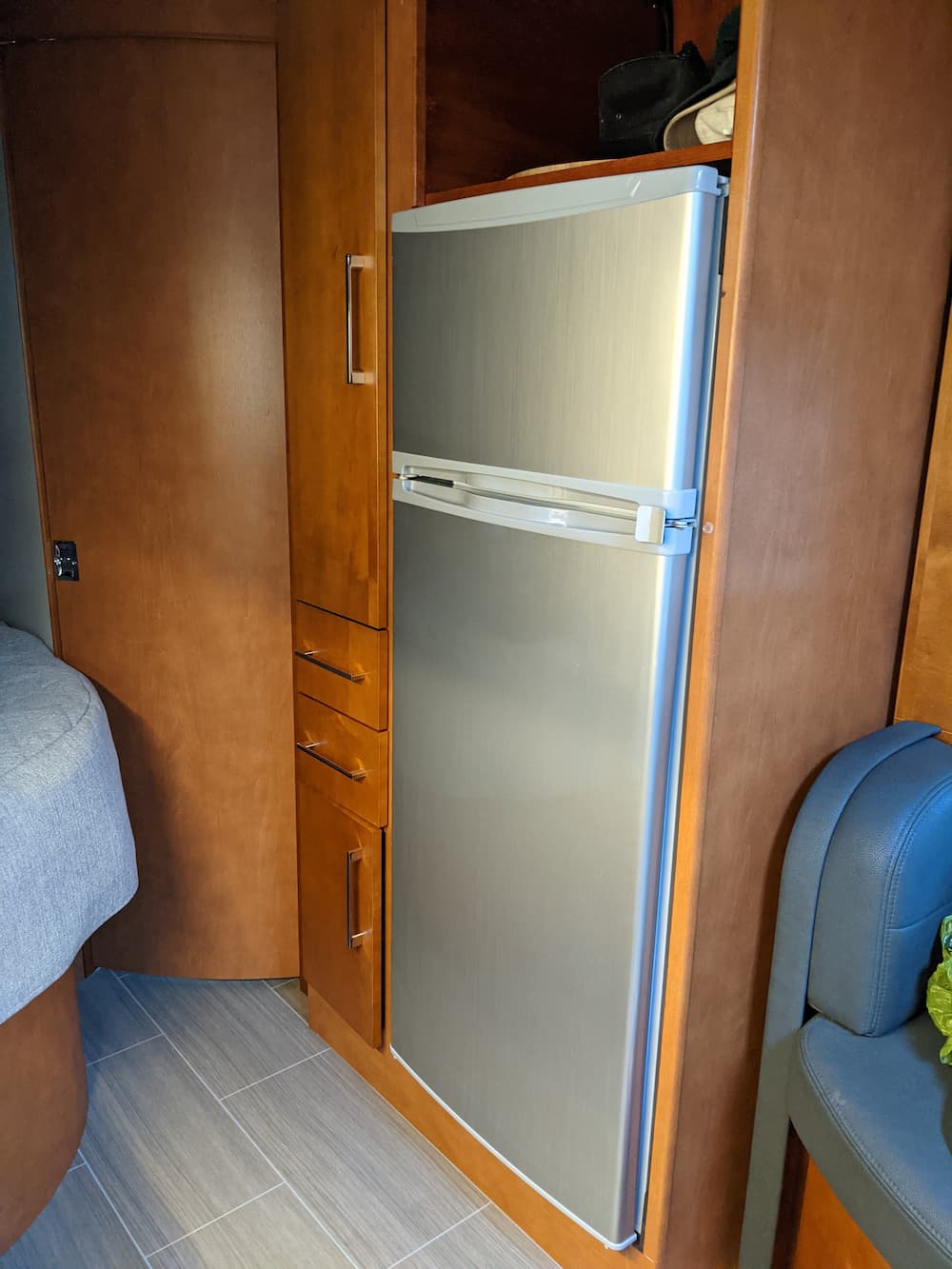
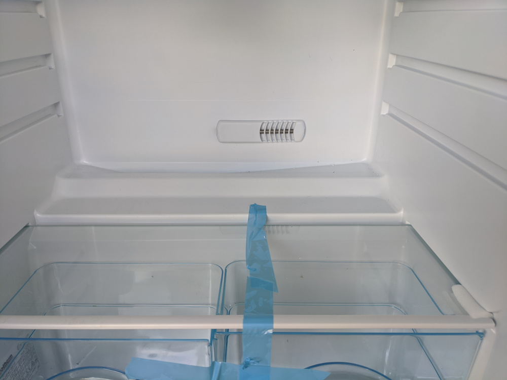
Finally, I slid in the refrigerator and it looks very nice:
The real nice cherry vent below the fridge is something I found on Amazon. The NovaKool came with a metal version, which would have been acceptable, but it was a bit mangled.
Also I realized that you’d have to slide the fridge part of the way out to remove it and perform maintenance, so I slapped a coat of cherry stain on the Amazon vent and 4 coats of polyurethane and it came out beautiful.
Postscript: September 2024
After using the fridge for a while, a couple observations.
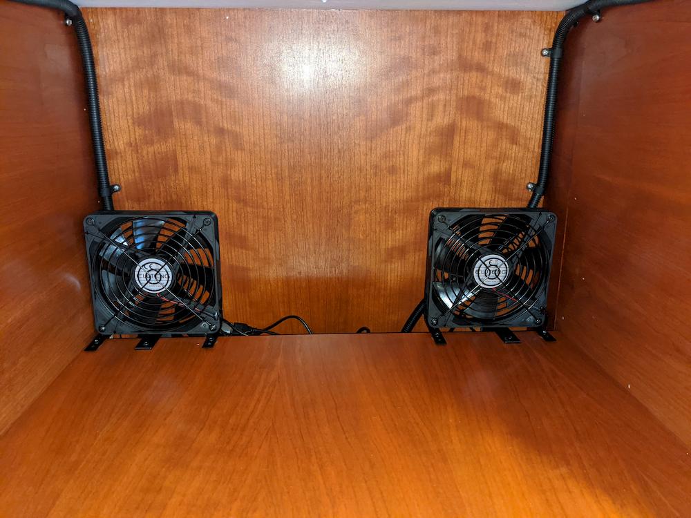
The top fridge compartment is working as well as I hoped. It will maintain a safe (34-40 degrees) temperature in every case so far, even at 95 degrees. Its very powerful and recovers from being opened and loaded quite quickly.
The freezer compartment is good, but not quite perfect. I would like to maintain it at zero degrees, just like a home freezer, and in warmer weather, that’s generally not possible. I can get it down to 5 degrees when the ambient temperature is 80, but have also seen it rise to 20 degrees when its extremely hot, parked with the AC off, and the sun is beating on that side.
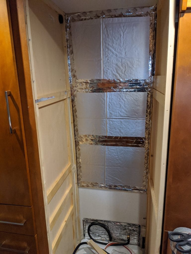
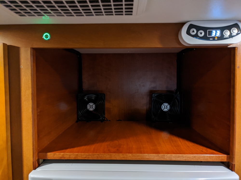
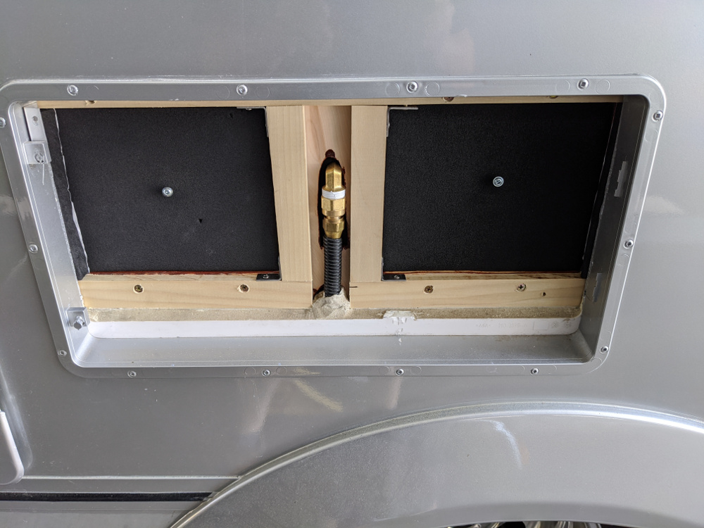
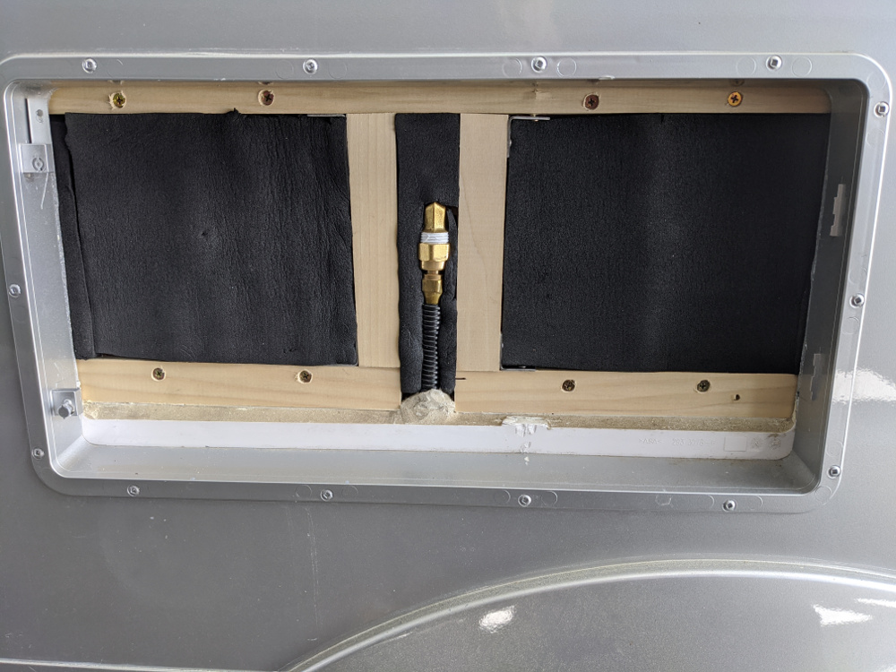
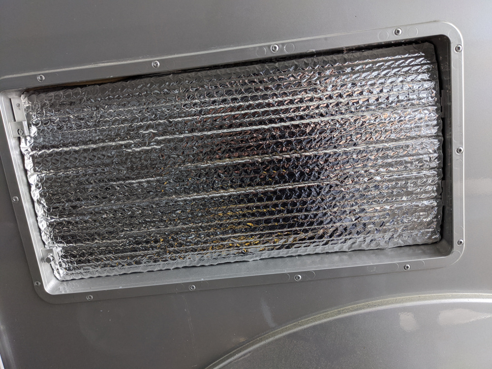
This is due to the fact that my Unity Corner Bed has quite a small area behind the fridge, and in the worst conditions, it heats up pretty hot. I feel certain that over time I can improve this considerably, and I am experimenting with different fan combinations behind the refrigerator – either exhausting straight up to the open shelf above or forward into the passenger compartment. So thats still a little bit of a work in progress but overall I am still rating the fridge excellent and my best so far.
Also, I was originally concerned that this lacked any kind of defrost line like my previous models. But during a 2 month trip – the frost, while it did frost some it never got bad enough to inhibit performance, so I am really pleased on that matter as I hate to defrost on the road.
Note: Please do not try this at home unless you have a good idea what you are doing! Connecting 240 volts to your RV would probably result in “very bad things” ! Always check that a new adapter actually is 120 volts with a voltmeter, and that it is wired correctly with ground.
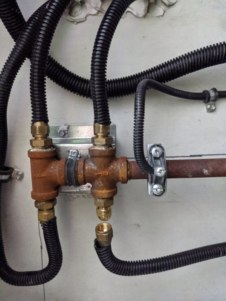
From time to time we stop off at a friends or relatives house and there is a convenient dryer outlet nearby, which of course we have no way to use.
Now, a standard dryer is 240 volts, and our RV is 120 volts, but that it is not a problem because the dryer outlet achieves 240 volts by using (2) voltage feeds combined, each 120 volts.
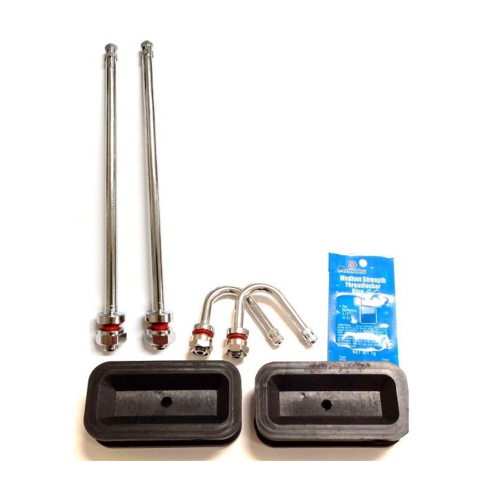
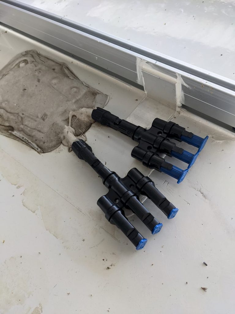
So we just need to use half of the dryer outlet.
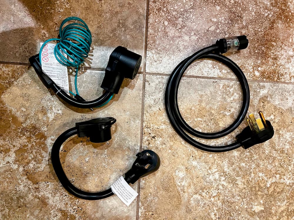
The picture above shows a few ways to do it. The bottom picture is the most straightforward way – its a simple adapter that has a 4 wire 240 volt dryer plug on one side and a 30 amps 12 volt RV outlet on the other. Just plug in your RV!
In case you have an older 3 wire dryer outlet, the picture on the top left is an 3 wire dryer adapter. The extra green wire you plug into the ground connection of any nearby outlet.
So with these two adapters (Amazon links all below) you can plug your 120 volt RV into any dryer outlet and enjoy the full 30 amps.
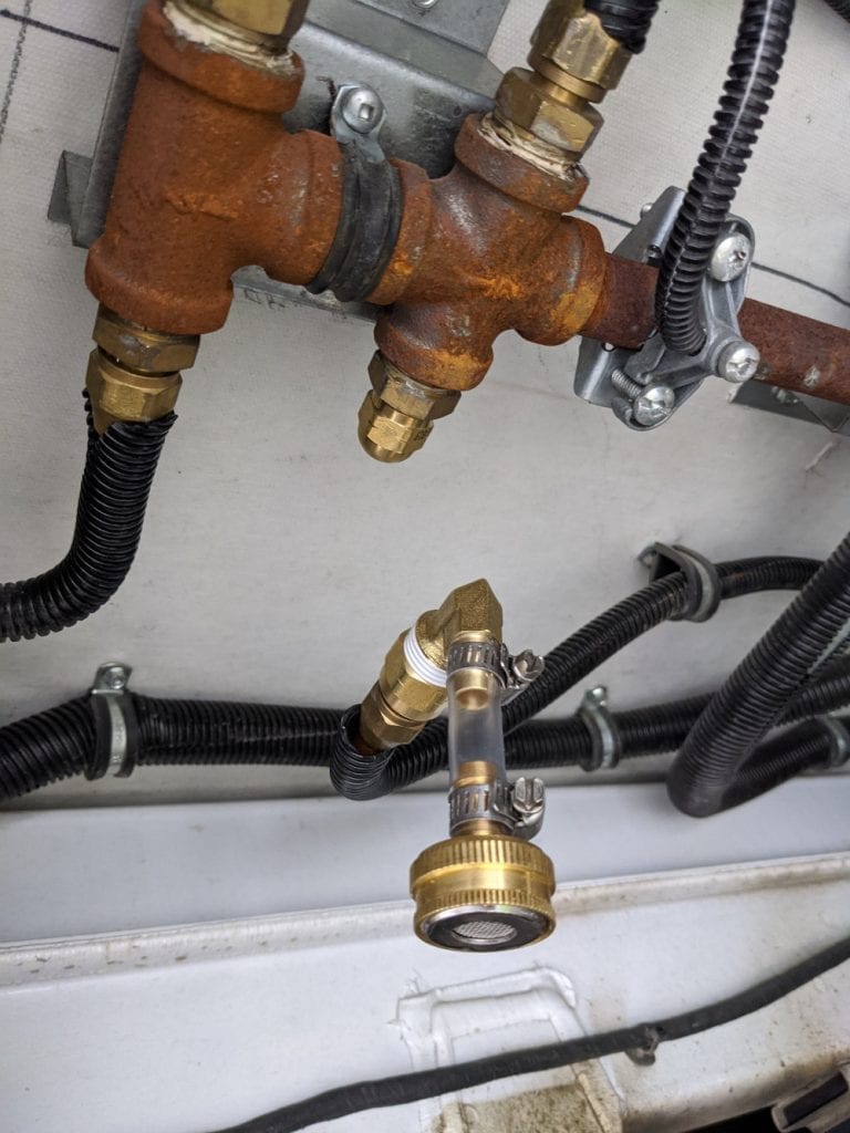
But I also have a brother who has a dryer outlet a distance from his driveway. So I made the adapter cable on the right. Its a standard 4 wire dryer cord that I connected to a heavy duty 20 amp outlet for a standard 120 volt AC plug. This will be used with his extra heavy duty 50 foot 120 volt extension cord to deliver up to 20 amps to the RV in case some extra distance is needed. It also can use the 4 wire to 3 wire dryer adapter if necessary.
It was fairly easy to make this adapter cable, since the 10 gauge wire just (barely) fits. It took a little patience to get the over-sized wires all in the holes to tighten but came out perfect. This is a safe adapter but you are on the honor system not to draw more than the 20 amps the 120 volt outlet is rated for! (The extra red wire is not used and I cut it off)
So now with this kit I can mooch off of friends as long as I want, at least until somebody wants to start the dryer.
Now that I have successfully “hacked” my RV refrigerator, I would like to improve the thermostat. My goals are:
Lower frost by lengthening cycle times
Remote internet monitoring and settings!
Add dual thermostats so the freezer can be monitored as well and the compressor started if necessary
Most of all, add the ability for something that engineers call hysteresis. This means, sure we can turn on the compressor when we begin to hit unsafe temperatures (around 40 degrees in the fridge or anything above 15 or so in the freezer), but how cold should we then shoot for?
Since we only have a single compressor, if we zoom it down to 32 degrees and then wait for it to get back to 40 until we turn it on again, we will have a nice long defrost cycle and all the ice crystals on the wall will melt and flush away. But being off for 40 minutes, the freezer may drift too high.
The factory thermostat works perfectly in the “average” conditions it is set for (probably around 72 degrees ambient). But if it is very hot or very cold, the fridge does not work ideally anymore, and in a nutshell that was the impetus for this project.
Since I have *way* too much free time right now, I kinda went overboard. But hey, safe cold food storage is real nice to have while traveling.
For this project I thought I might use an Arduino board. I have never seen one before but was vaguely aware of the low cost tiny microprocessor boards that are easy to use. After a little Googling I selected the Arduino Nano 33 IOT (Internet of Things) pictured:
Why use a microprocessor for a thermostat? Well the Adruino has both Bluetooth and WiFi. I already have the super nice SensorPush Wireless Thermostat in both my refrigerator and freezer. So my idea was to monitor the Bluetooth thermostats and then start and stop the compressor accordingly.
The first little bump in the road I found setting this up was, while the Nano 33 has WiFi and Bluetooth, you can’t use both at the same time! At least without a whole lot of hacking.
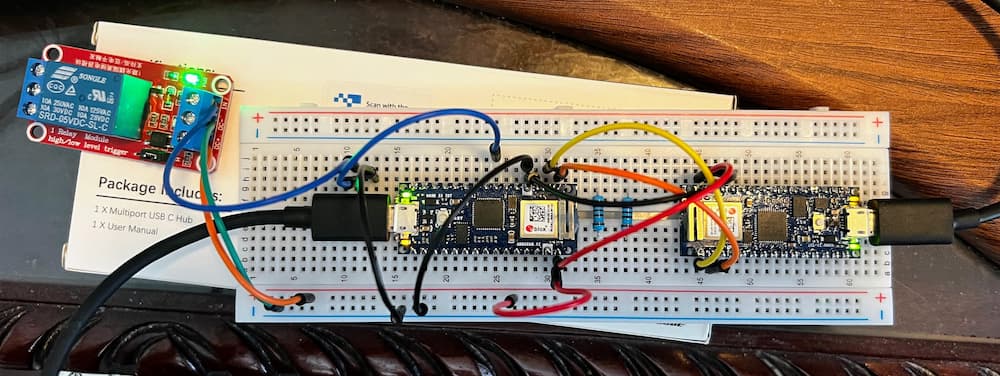
So my solution was, just use 2! So here is a breadboard of my experimental project. (Later on I will solder a permanent version for bumpy roads; this is just for testing).
So, what we have here is, the board on the left will control the refrigerator. As you can see its wired to a 5 volt relay that will connect to the Secop thermostat contacts. This board reads the current temperature via Bluetooth of both compartments, and starts or stops the relay as necessary.
The board on the right is totally optional. This one is the “IOT” (Internet of Things) part of the setup. It exchanges data through a serial UART connected to the companion board, and relays information to the Arduino Cloud where I setup this nifty dashboard.
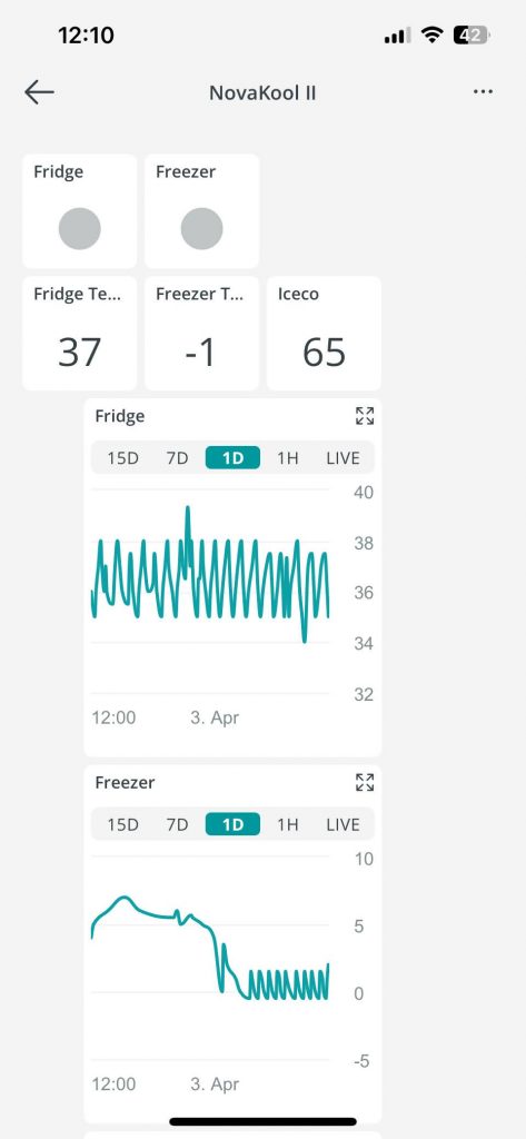
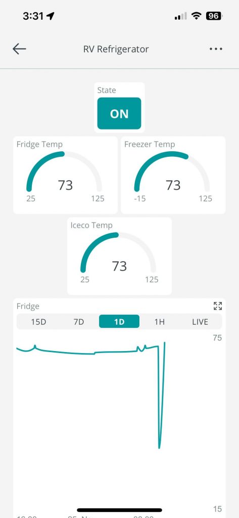
The first page shows if its running or not. It also shows you the current temperatures. (The third sensor is my Iceco wine cooler). The graph shows you the historical temperatures as well.
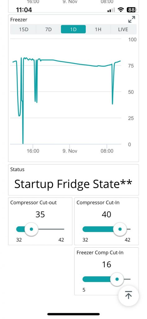
The second page of the App shows the freezer historical graph. And at the bottom 3 settings:
Compressor cutout – stop the compressor at this temperature.
Compressor cutin – start the compressor at this temperature
Freezer cutin – start the compressor if the freezer reaches this temperature
Sounds confusing at first, but makes sense if you think about it. You primarily want to keep the fridge between 35 and 40. (I keep these sensors in the warmest parts of their respective compartments).
The freezer you want as close to zero as possible (sometimes its well below zero), but occasionally, if the compressor is off for a long time (usually during cooler weather) the freezer can start to get too warm, so at 16 degrees I will start the compressor even if the fridge is not calling for it.
I can tweak these settings later. And I may have to play with them if in different climates. In 100 degree weather for example, I might find that the fridge never gets below 35 and thus runs continuously, so I could bump it up a degree or two. But my hope is that 90% of the time I would never need to change anything.
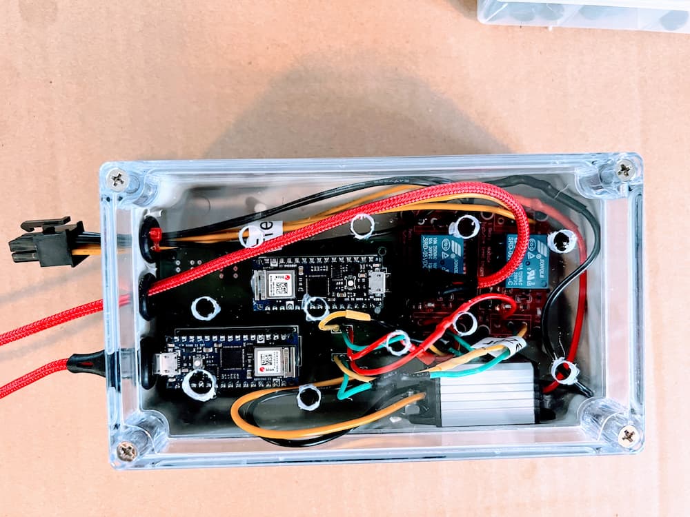
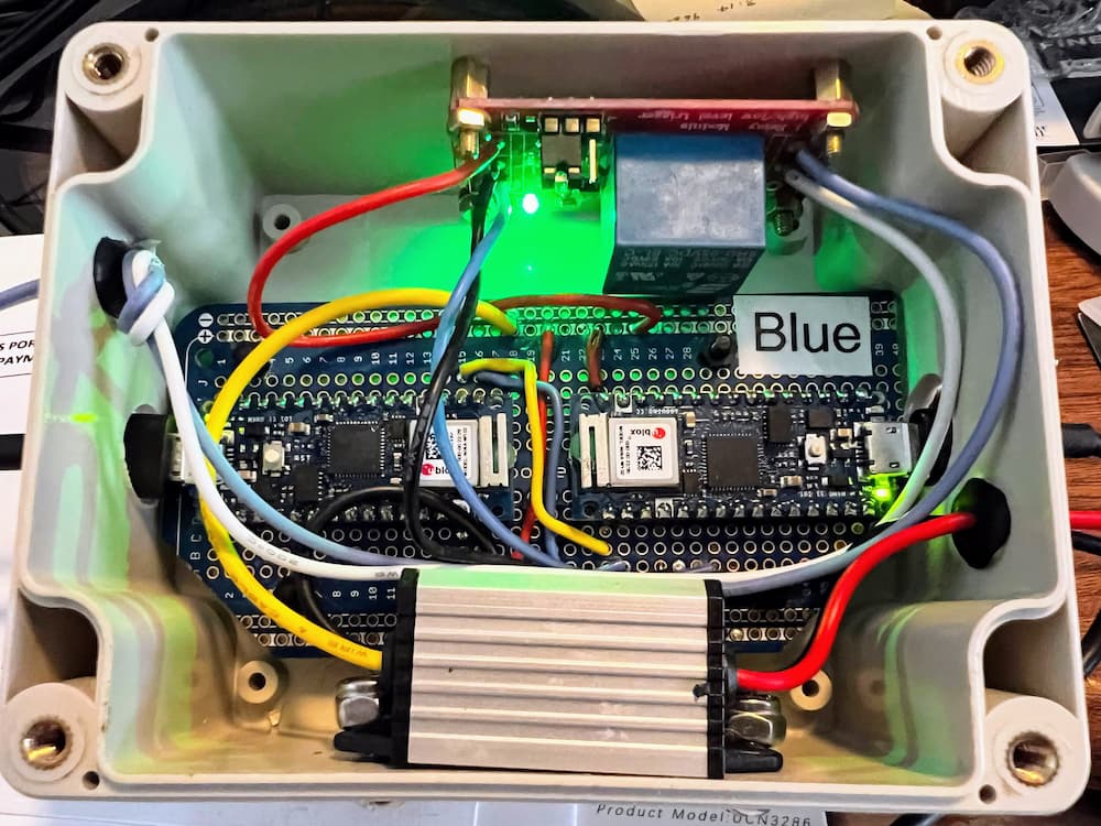
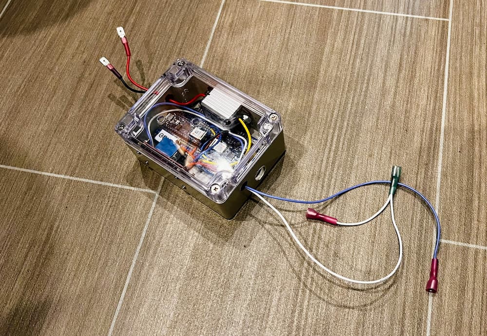
After a bit of programming I have a prototype that seems to work pretty good, so I soldered together a more robust version:
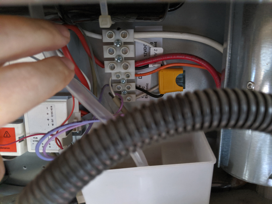
This permanent version has a small “buck” converter that will convert my 13-14 volt RV battery to the 5 volts needed, the relay module, and the (2) Arduino processor boards.
The blue and white wires connect to the refrigerator and the red and black wires are for power.
I’m off to run some preliminary tests connected to a real fridge, and see how it works, but so far its all looking great.
I will post the results in the coming weeks and month, as I test this in real travels…
(Later the same Day)
Holy Crap it works! Fridge cooled down in about 2 hours. Compressor cut off at 36, back on at 40. Freezer ranged from -8 to 7 degrees. Defrost (off) cycle was about 30 minutes, so these are good settings at this pleasant weather of 75 degrees anyway…
Ever since I installed my Isotherm Cruise 219 I have been able to travel anywhere in the USA, in any weather, and have food safely stored in my refrigerator and freezer, which is more than I can say about my factory Dometic propane fridge.
Still, its not perfect. If I had it to do over again, I would have selected a dual compressor fridge. The extra power and precise ability to tune both compartments is even better.
I’ve had numerous issues with my fridge, some self inflicted. The self inflicted one is, I purchased this guy:
This is the very cool Secop “ITC” controller, with many features and looks nice on the wall. As I soon discovered though, it had a major drawback.
Rather than the crude mechanical thermostat that is standard equipment, it controls the temperature with a probe and its rather precise. The problem is, it caused me to have a tremendous frost problem – as bad as the Dometic. Thats because it short-cycles the compressor continuously, running in 15 minute or so cycles, with an equal amount of “off” time. This results in a continuous ice coating of the back wall. Its never off long enough to have a melt session.
This led me down an endless rabbit hold with the manufacturer, who started sending me new doors and such in the useless quest to seal the refrigerator better.
But it turns out frost is not really caused by bad door seals as the Internet seems to believe. Home refrigerators have heaters and perform defrost cycles daily. (And every time you open the door a blast of humidity enters, so its somewhat hopeless to keep humidity out.)
RV refrigerators have no such ability. The only way to get it “frost free” is to turn it off long enough for the temperature on the back wall to rise close to 40 (which is still a safe zone) and then enjoy the massive ice melt. The crude mechanical thermostat did a great job of that – by virtue of it running the compressor longer – and then the resultant longer downtime. So the trick to get the fridge somewhat frost-free is extended run time followed by extended off time.
So you’d think I could just remove and put back the factory thermostat, right? Well, no. It turns out the ITC reprograms your Secop compressor!
Once reprogrammed, it will no longer work correctly with a mechanical thermostat. You could replace the Secop controller of course, but I started thinking that what I really need is a better thermostat, that more accurately would generate defrost cycles, and for starters I would have to reprogram my compressor so I could get rid of the ITC.
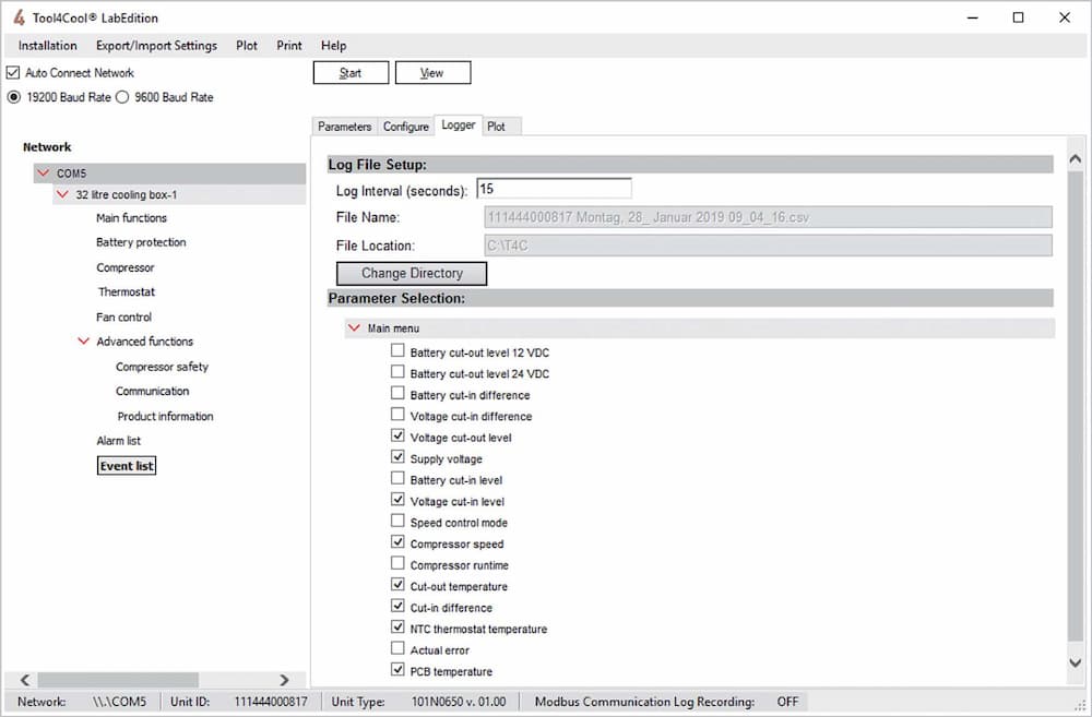
And that search led me to the discovery of this nifty software aptly named “Tool4Kool”:
This package is designed for refrigerator manufacturers to program the Secop compressors on the assembly line. There are a lot of useful settings such as battery cutoff voltages and such, and most importantly the thermostat type. I wasn’t sure if you needed to buy a key to use the software, but it seems I had further to go down the rabbit hole.
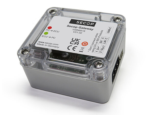
The next step is, I needed some way to actually connect a refrigerator to my laptop PC, and it turns out they have a brand new product just for that:
This is the all new Secop-105N9518. Its a gateway that uses a standard USB-A so you can connect directly to the Secop controller. Again, designed for refrigerator manufacturers. Neat! Except you can’t actually buy it in the USA (we don’t make any Marine/RV refrigerators I guess).
In fact, because its so new you can’t actually buy it anywhere in the world practically! Maybe its just not advertised – you have to be a refrigerator factory?
I did eventually find it here:
Hello! This is Jabsales in Maribor, Slovenia. These nice folks have it right on their website. The price was very reasonable (shipping not so much). They required a wire in advance but to their credit shipped the next day, so it was a very good buying experience (not counting the hurt of the overnight international Fedex).
So with software and interface in hand I hooked it up and, it worked!
Took4Kool did everything it promised and more. To my surprise I didn’t need any software key and moments later I was reprogramming the Secop compressor.
The first thing I did was, most manufacturers (including Isotherm) have a resistor on the mechanical thermostat connection. This resistor sets the maximum thermostat speed. I verified mine had the correct resistor for maximum (3500 rpm).
But I’m hoping to build a better thermostat, and I don’t want to ever run the compressor at less than max anyway, so I removed the resistor jumper, and reprogammed the compressor to just look for a straight on/off at the the thermostat contacts. And then I programmed the Secop to hardwire the compressor speed.
This will allow me to go even further down the rabbit hole, and make a thermostat that is more to my liking. My thermostat will have specific programmed defrost cycles, and be tweaked for my particular refrigerator. More on that to come soon…
November 2023
Still working on my new thermostat. In the meantime the Secop gateway stopped working, complaining that I needed the dreaded product key. Fortunately they list a bunch of the right on their product page, and the “general” one of ZH3TT6RBAD1GW8G68ZM1N8G62ZMCORVB3OEGBL12UZNAR worked.
I’m pasting it here in case it disappears from the internet some day, but as of now it works fine. It seems to me that the gateway is powered entirely from the laptop USB, so leaving it connected semi-permanently is just fine as it turns off anyway once the laptop is removed.
I’ll post more on my experimental thermostat soon, but in the meantime here is the early development version. This is just for testing, I’ll obviously have to solder something substantial to go bouncing down the road in my RV. It uses (2) Arduino Nano 33s and a 5 volt relay to turn the Secop compressor on and off. The processor on the left handles the Bluetooth connection to (2) Sensorpush Bluetooth sensors, and the one on the right handles the control panel and Internet (WiFi) connection for remote control and monitoring.
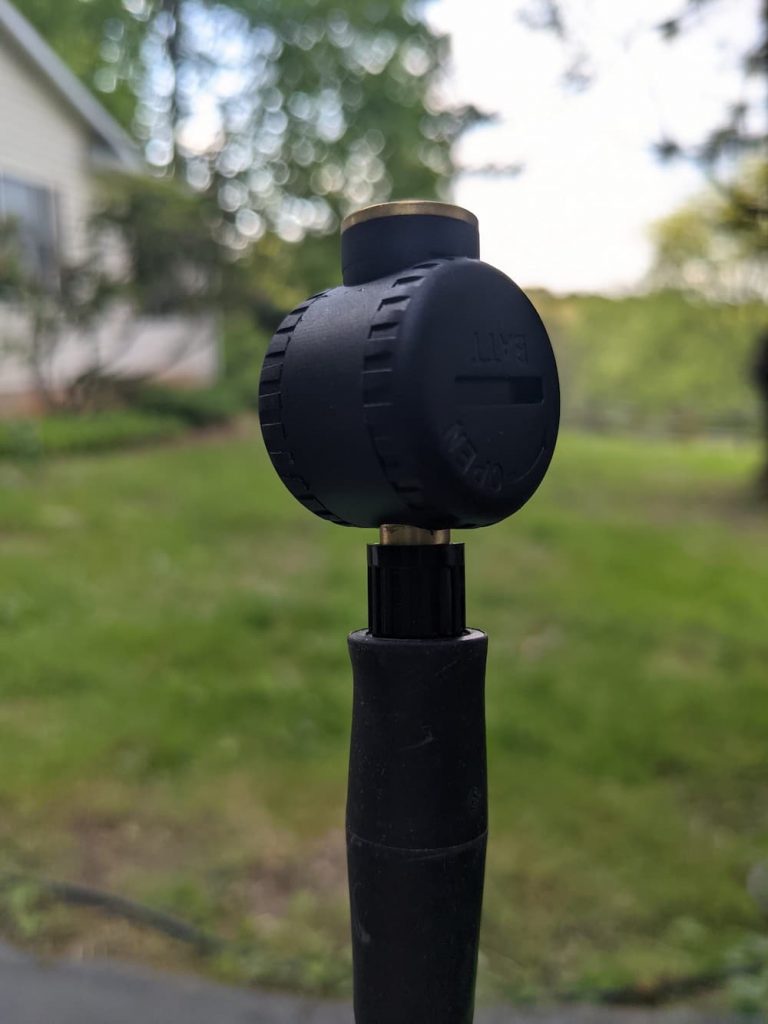
The “Fantastic Fans” in our RV work pretty well, but are definitely less than fantastic. The main issue is that water can come in when open. So they have elaborate rain sensors which work perfectly to close the fan at the slightest drizzle.
Which is a major problem when trying to sleep with the windows open. In our RV bedroom the fans cause a steady breeze in the window. When the fan closed the tiny bedroom can quickly become stuffy as the breeze stops.
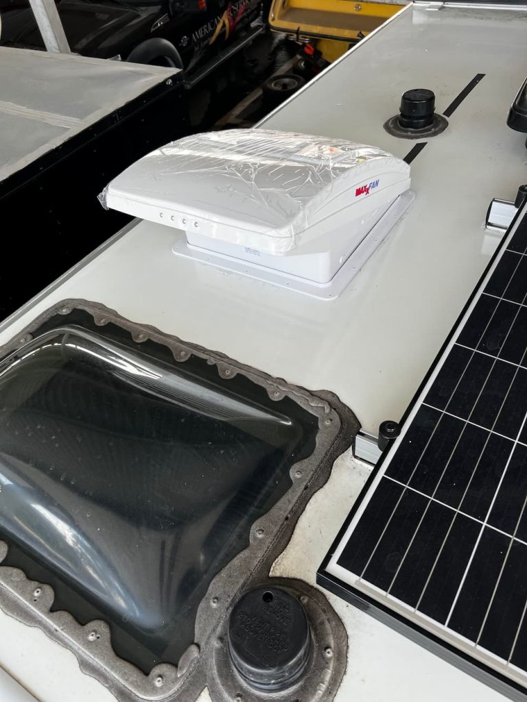
One solution is to just cover with a huge shroud. That was on our radar, until we discovered the “Maxxfan”. This fan is pretty slim and opens in a way that sucks in air from underneath the shroud, eliminating the need to ever close. It also has a lot of extra features such as 10 speeds and a reversing ability.
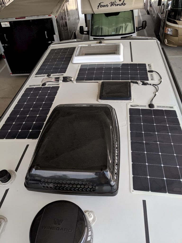
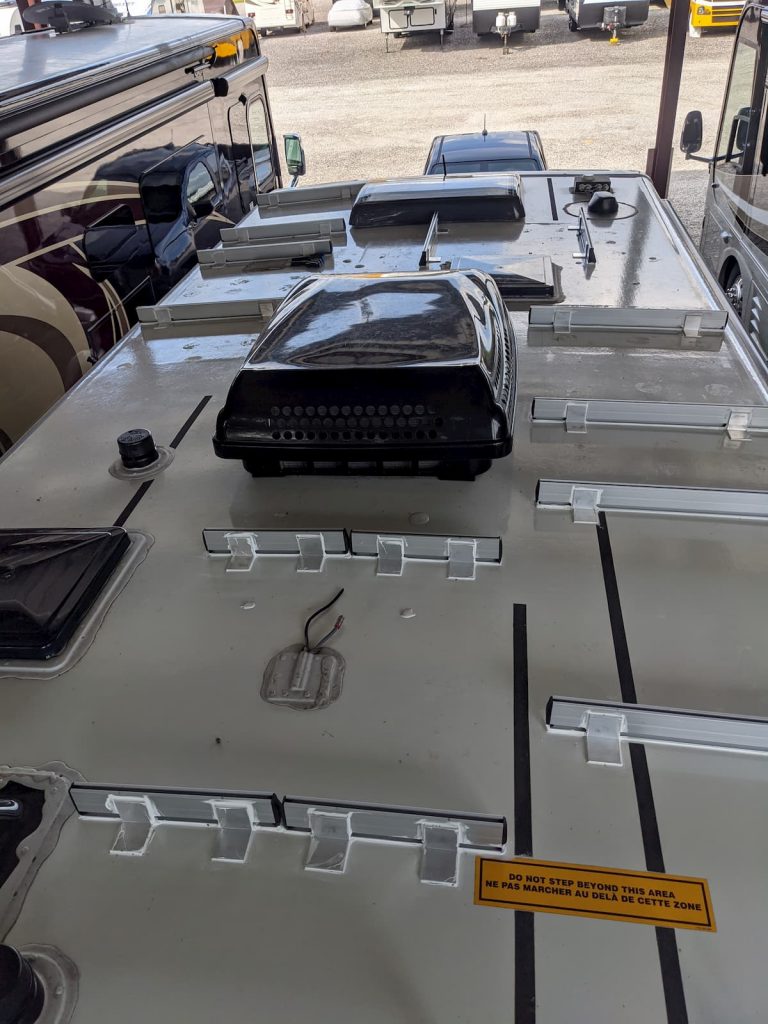
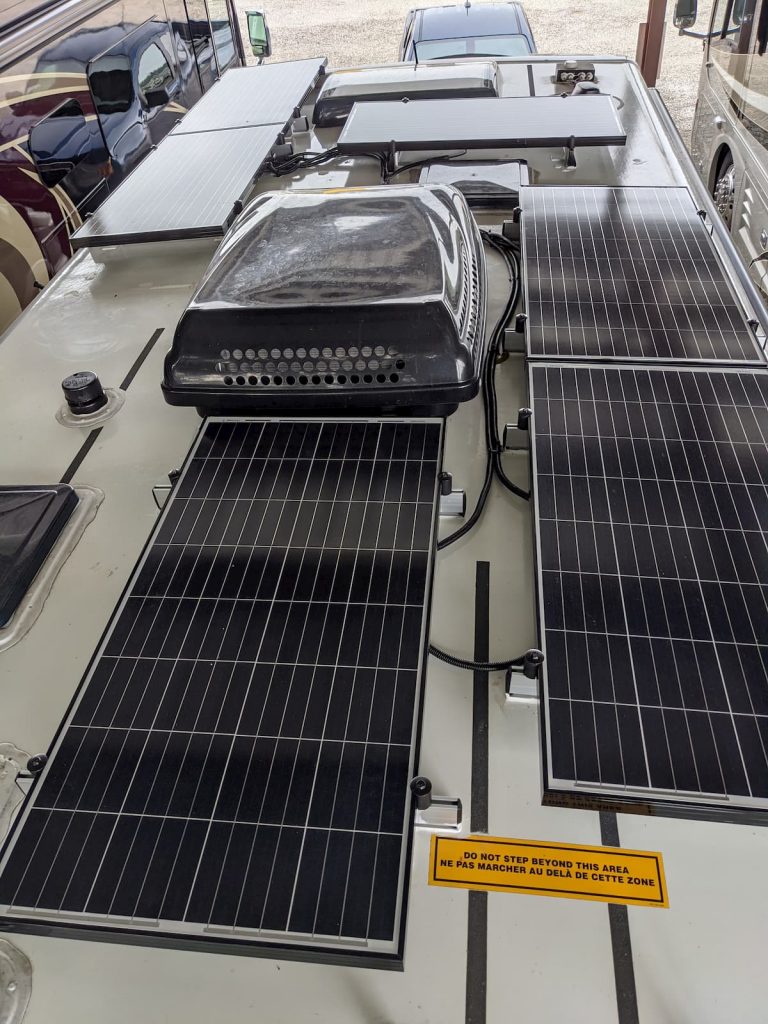
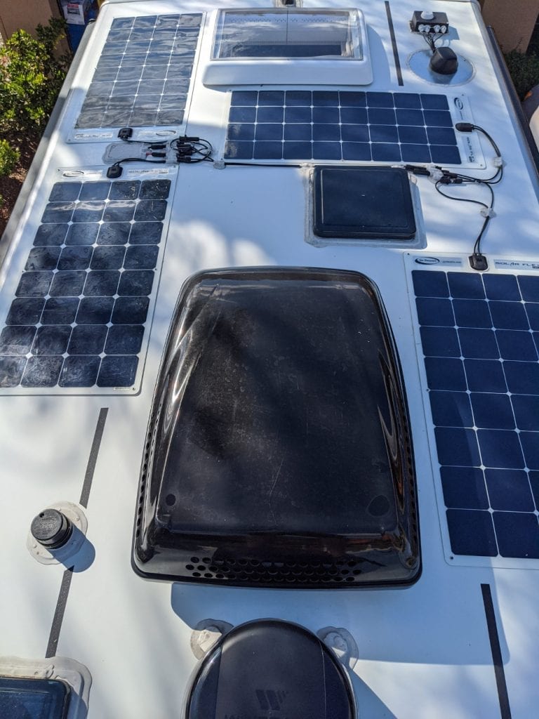
Unfortunately its larger, and my galley fan has solar just to the rear. But the bathroom fan has plenty of room aft, so that is the one we’ll be installing.
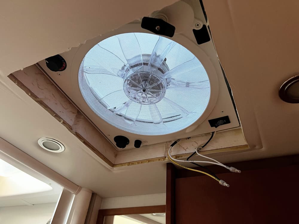
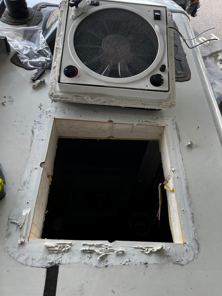
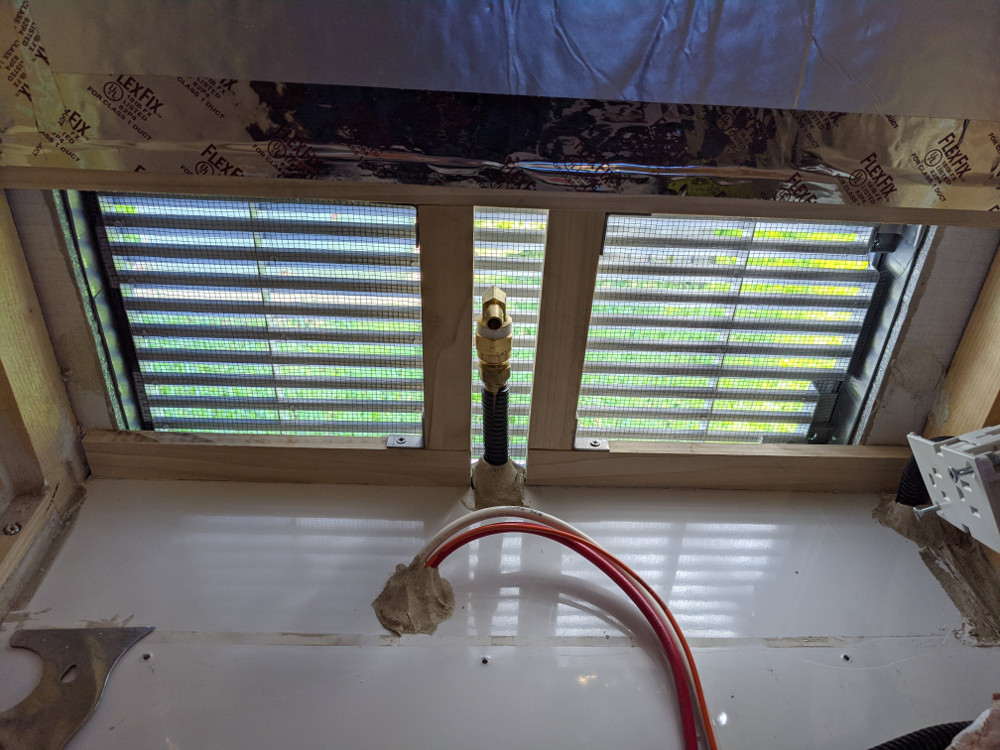
So lets get started! Here is the before pictures:
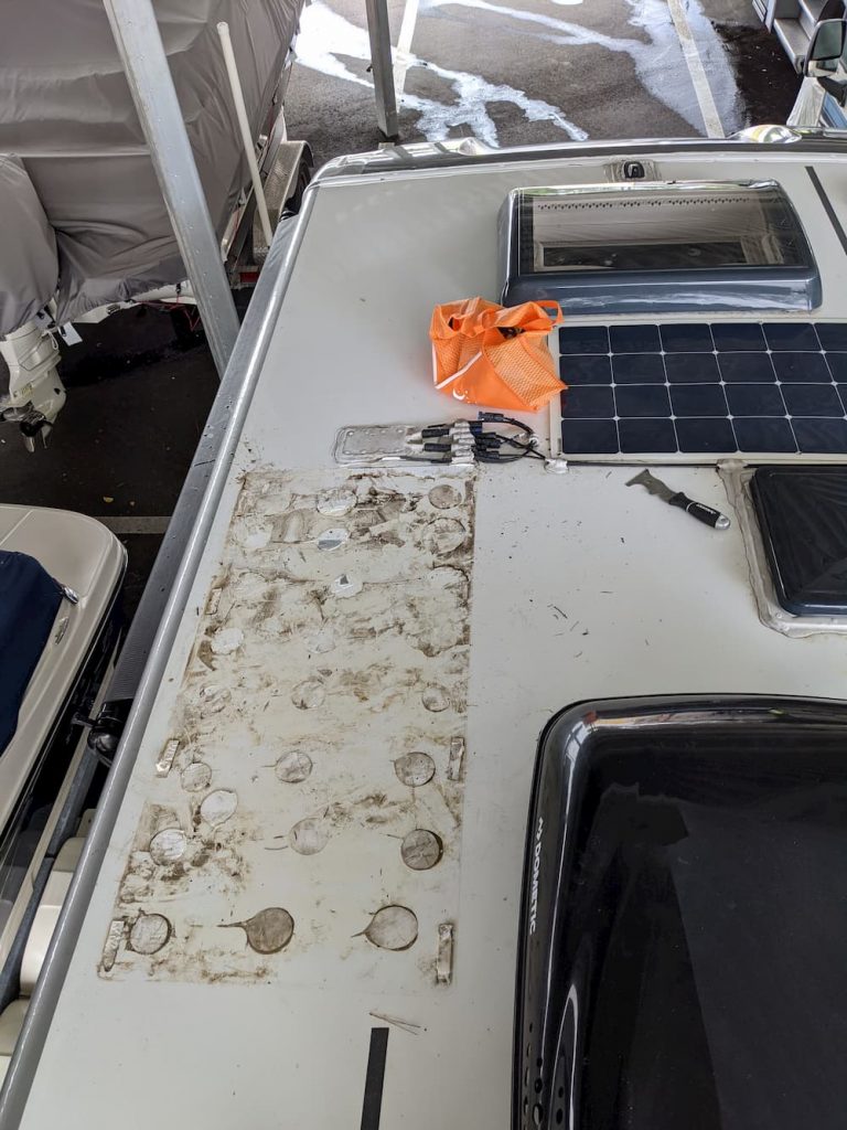
And underneath, after I removed the 4 screws holding the ceiling trim ring:
The first step is to remove all the screws from the roof. You can see the heads on some but I used a scraper to pry back a layer of Dicor first and then removed all the screws. Finally gently prying with a scraper after cutting the caulk around the edges.
Its was actually quite easy, and then you gently remove the whole fan assembly. (First cut the wires below of course.) In theory you should turn off power, but I was careful not to cause a short.
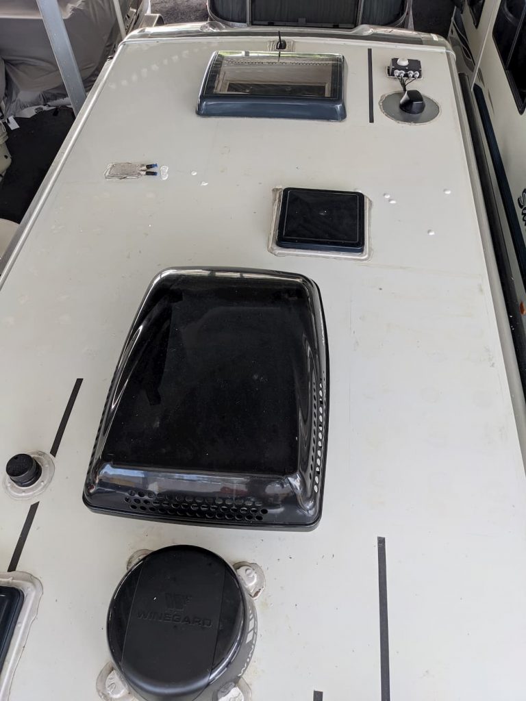
After that a little bit of preliminary scraping with a “5 in 1” scraper tool from Home Depot.
Its not a bad job. I used some alcohol, the scraper, and some elbow grease, and it was clean pretty quickly. It doesn’t have to be flawless as you are going to immediately cover the hole anyway.
Nest I did a test fit with the trim ring and dropped the fan on, just to double check everything. It comes with pretty good instructions. The safety wrap is still on the fan here. Towards the bottom you can see the two screw holes that secure the fan to the external trim ring.
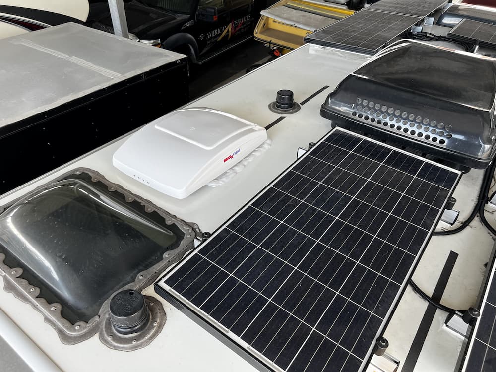
The next step is to glue and screw the topside trim ring on. The instructions recommend applying caulk (Most use Dicor) and that appears to be what LTV did for the old fan. I thought that might be messy as all the caulk shoots out all over the roof as you tighten it, so I instead placed 1″ eternabond tape on the bottom of the trim ring before pressing it down.
In hindsight, both methods have their advantages. The eternabond is potentially less messy but that stuff is so sticky its annoying to use. Also once the trim ring touches the roof you cannot reposition it with eternabond.
After sticking down the trim ring I installed all the screws and then finally used a full tube of self leveling Dicor to cover all the edges and screw heads.
There are 4 screws that hold the fan to the trim ring. The instructions said to push the metal clips all the way down, but on my fan they all had to be backed off about 1/8″ for the screws to align. From the sides I used a pointy awl tool to align the metal clips to the screw holes.
Inside, you are supposed to cut the trim ring to fit the slope of the roof. The old fan trim ring was near identical and still fit fine, so I simply reinstalled the old ceiling trim ring after connected the 2 wires and crimping the connectors on.
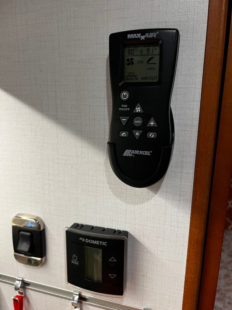
Also, you get a remote control which I mounted in the galley. The remote is nowhere near as useful as it could be because it uses optical transmission. So you have to remove from the holder and point it at the fan.
Other than that minor annoyance this was a quick install and a really great addition. It sounds minor, but being able to use the fan continuously is really important. For example, in addition to sleeping comfort, in mild weather we can leave the dog in the RV and not worry about the fan shutting off.
Here are all the parts and supplies I used for the job. Note that there are several variants of the fan (white or black and “deluxe” or manual. (I bought the better “deluxe” model in white.)
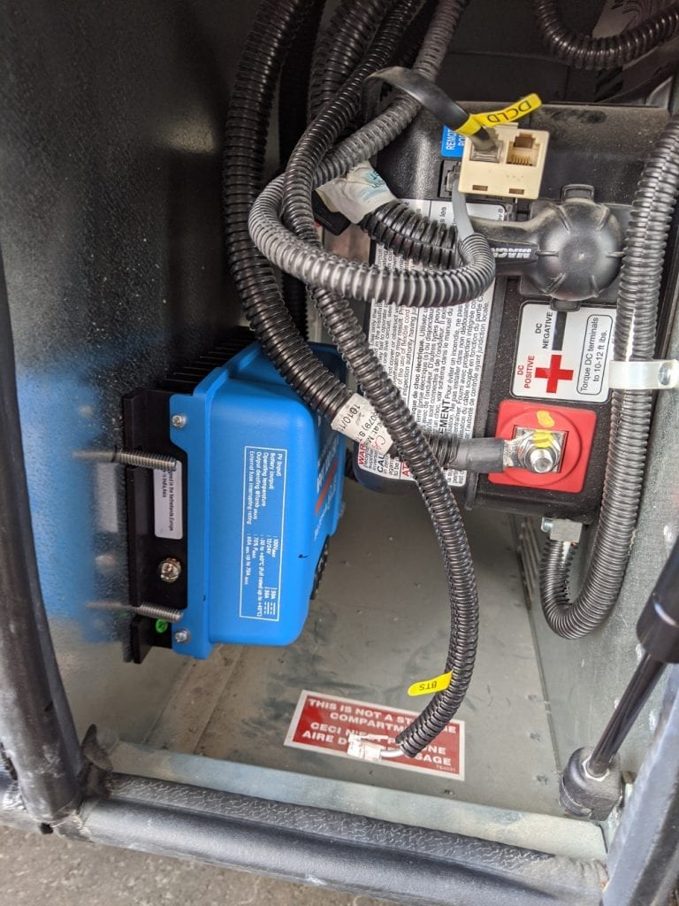
I previously installed a Renogy 40 amp DC-DC charger. It worked fine, but had limited settings and no Bluetooth. My new batteries want a low absorption charge set at 13.8 volts which the old Renogy can’t accommodate.
Also I would like to have a reverse DC-DC charger to keep my Mercedes battery charged while parked.
It seems a bit silly to install two DC-DC chargers, and a relay to prevent a loop.
Enter the Rego. This is the first bidirectional charger that goes both ways. It will charge your house batteries or your engine battery, depending.
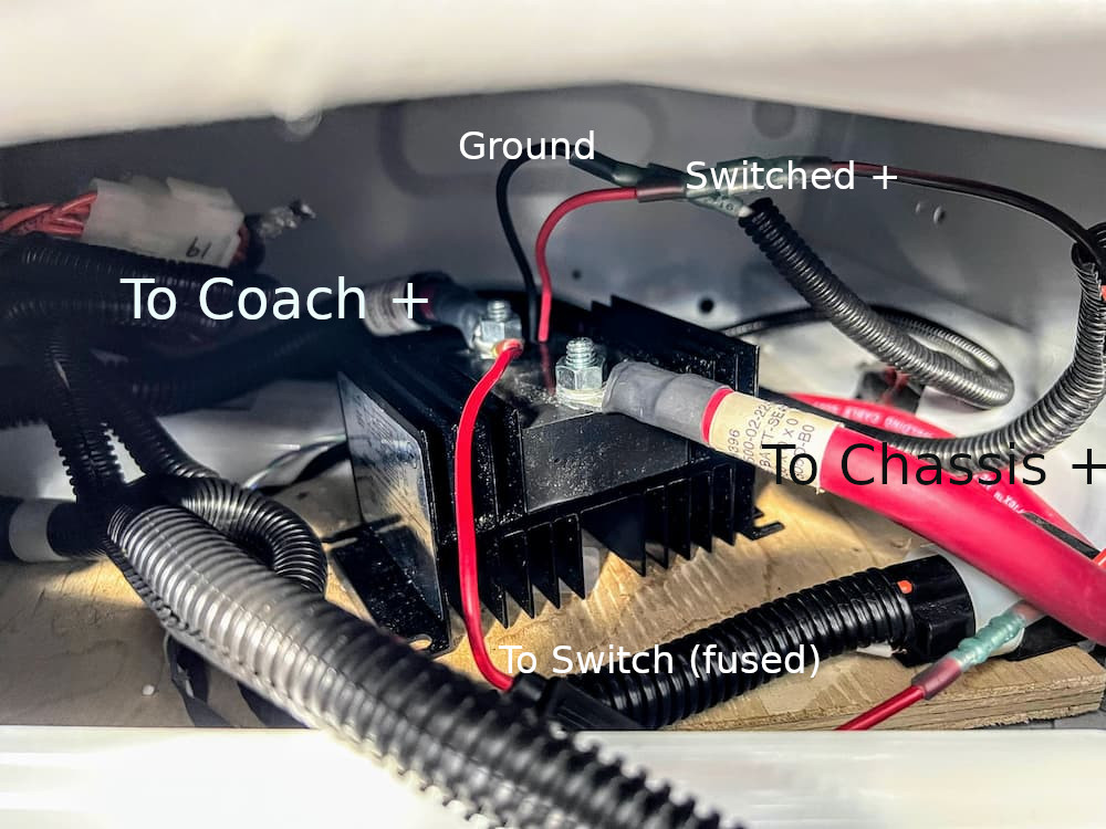
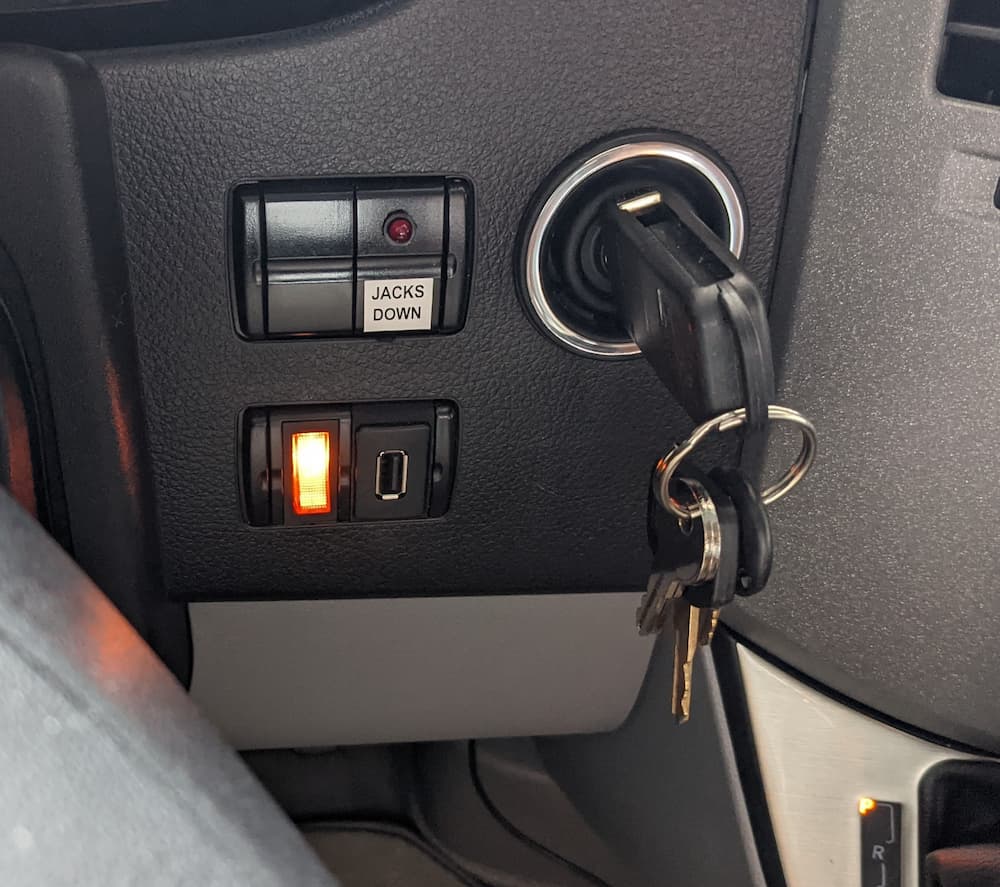
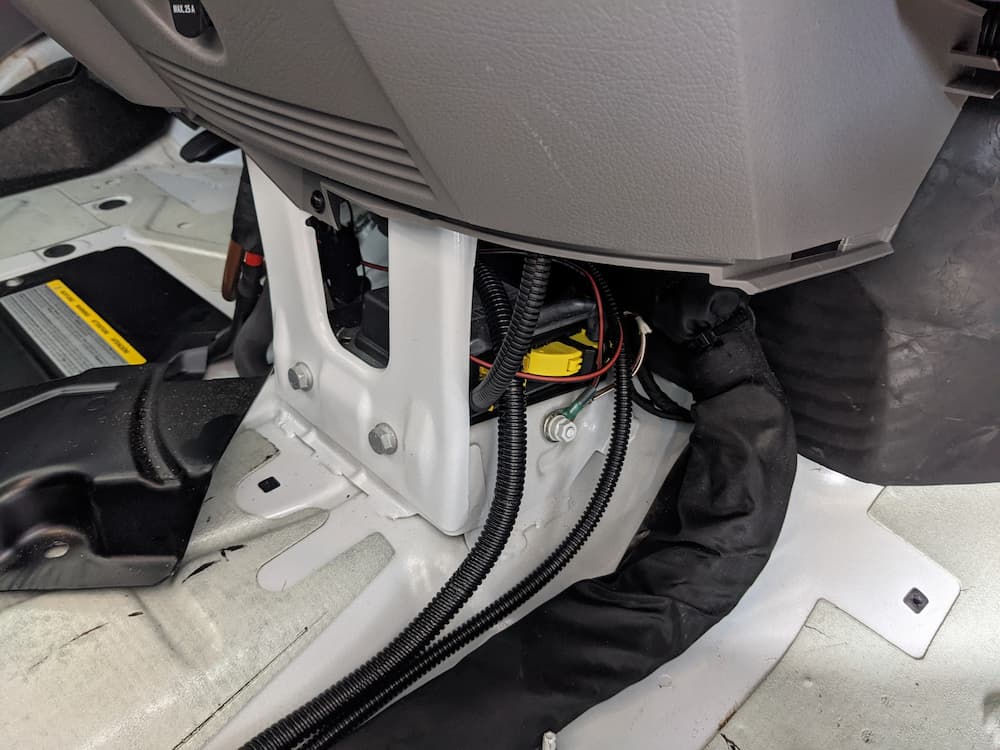
I want to preserve the DC Charger Lighted Dash Switch that I previously installed, so I will need some kind of relay to disconnect the starter battery.
I could use the existing Cole Hersee 200 amp relay that I installed way back. It uses about 1/2 amp though, and I don’t fancy leaving it activated for months even though its rated for continuous duty.
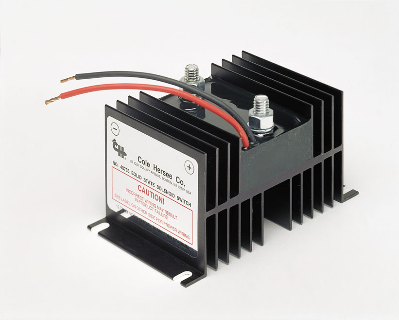
So its a bit of overkill, but I bought this guy:
What we have here is a “Solid State Solenoid” (presumably MOSFET?). The advantage is – rated for millions of cycles, no arcing, and a current draw that’s almost too low to measure – I think .05 amps. Its very expensive, but you can find it for under $150 is you shop around.
You could find something much cheaper on Amazon I am sure. But when I select electrical products for the RV, I prefer absolutely top quality. Cole Hersee was always a great brand (recently acquired by Littelfuse, another well known brand) so I know I am getting a quality build.
The relay should be extremely simple to install. I am going to remove the existing battery isolation solenoid under the seat and basically drop this in instead. The only wiring change is that I don’t want the existing IRD. That device turns off with the engine, so I wouldn’t get a bidirectional charge. Instead I will power this “relay” from the house battery, so its always available as long as I don’t turn off the house batteries.
Neat!
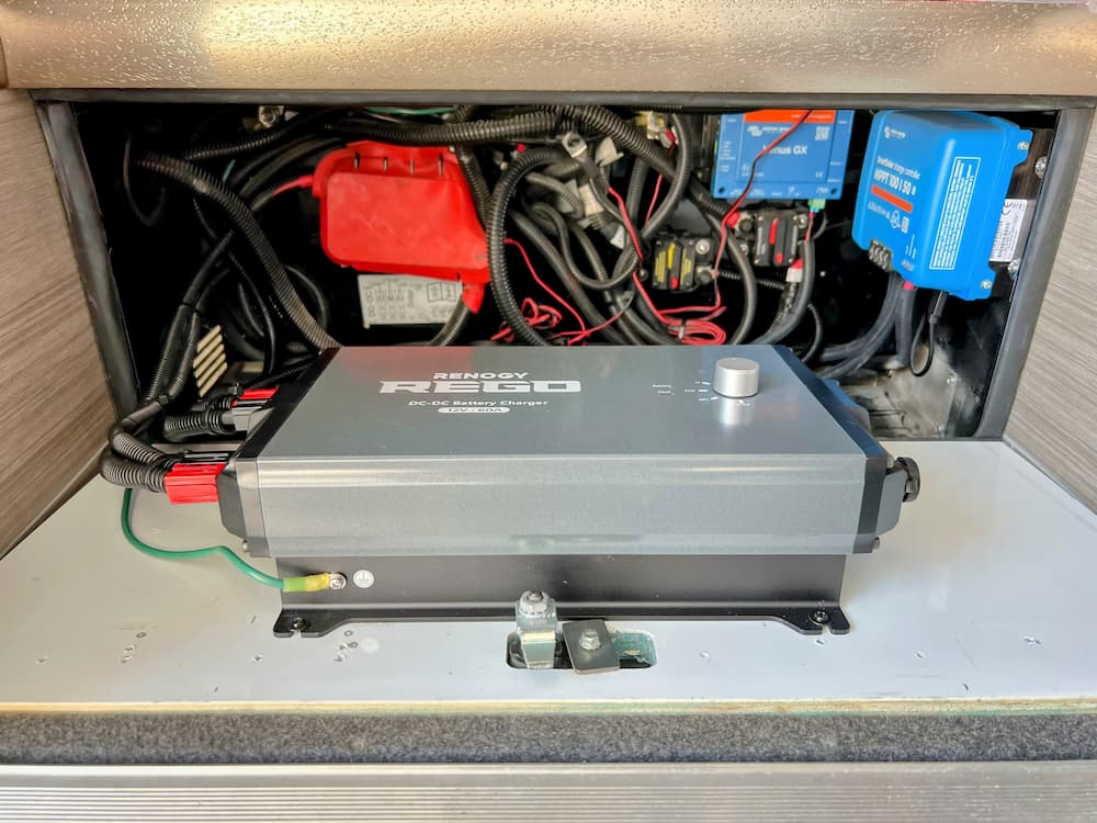
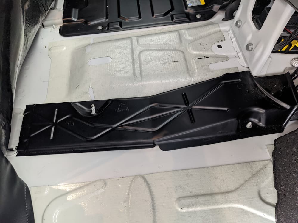
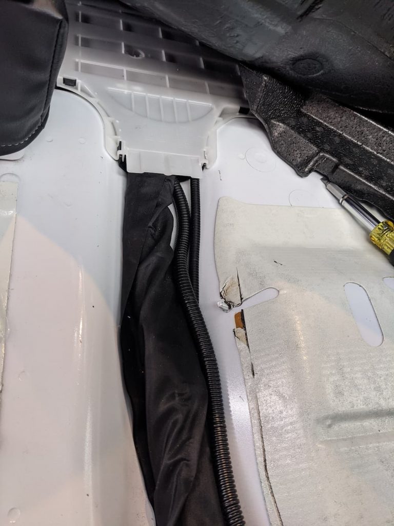
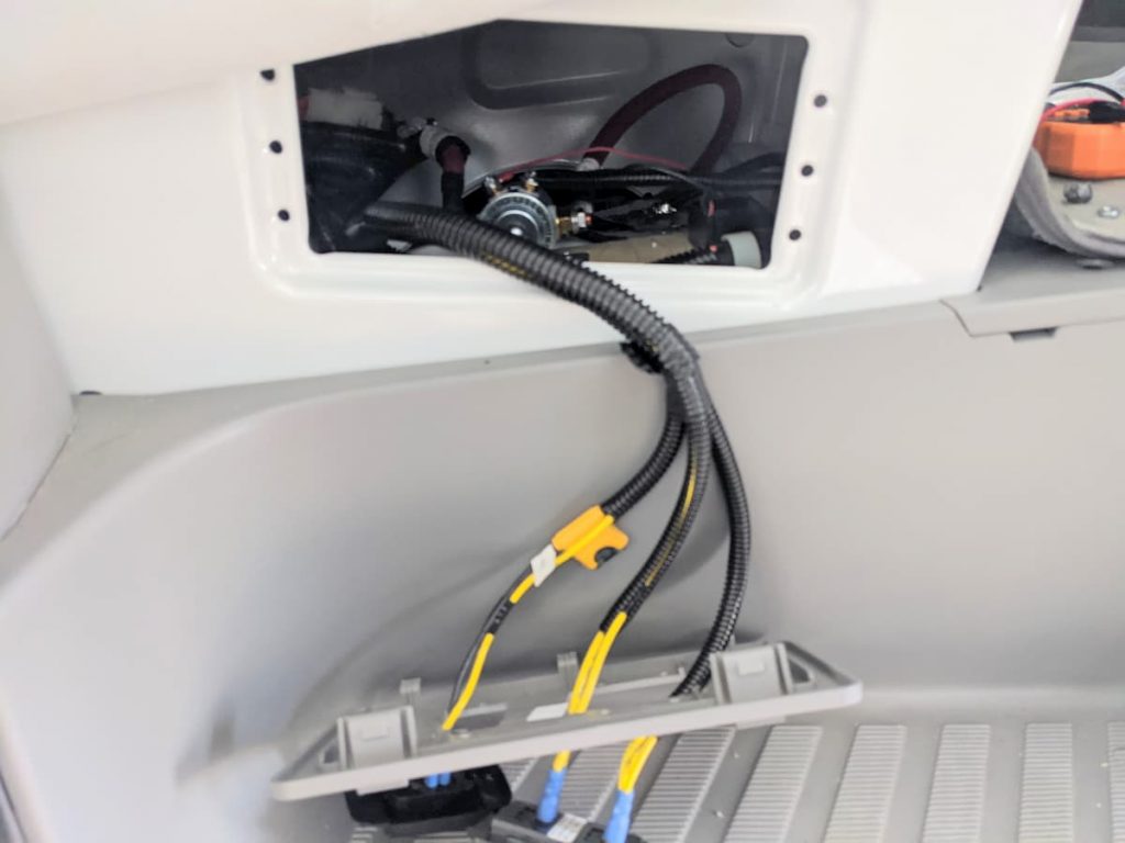
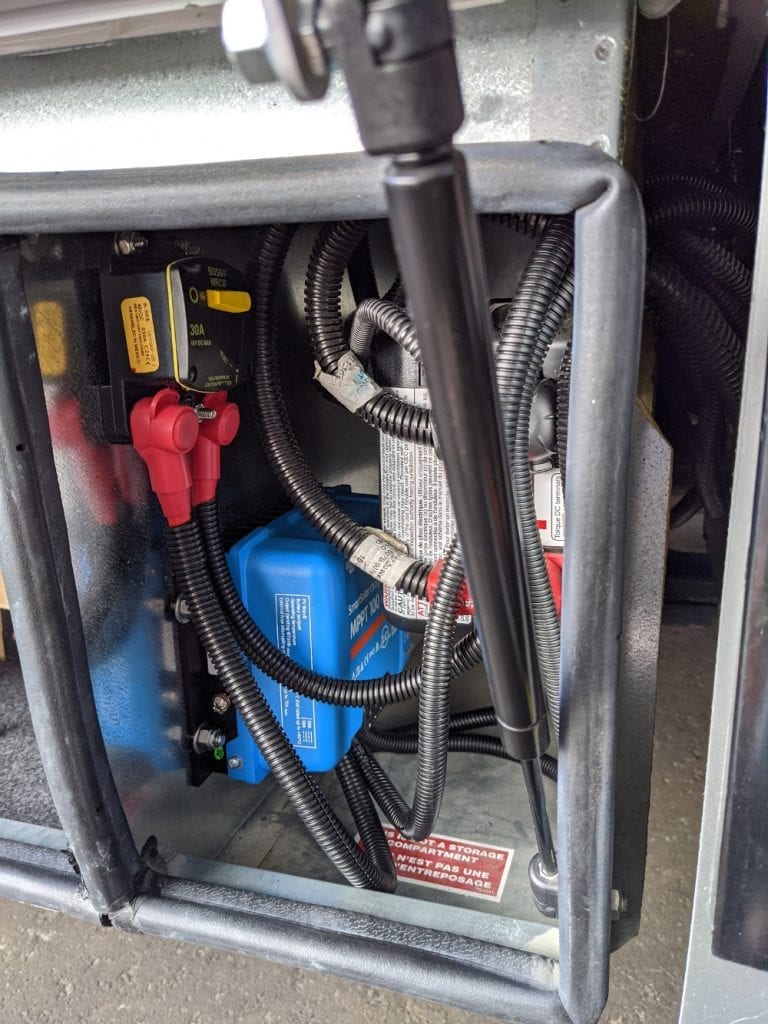
The Rego itself is painfully large. They want you to mount is vertically. While I suspect that’s not 100% necessary, I have a pretty good spot chosen. What used to be the battery compartment under the steps is partially empty now that I installed 400 AH of Discovery Lithium. So I’ll mount it in the old battery compartment which is perfect because that’s where all these wires terminate anyway. This compartment is well ventilated and gets caked in road dust so the Rego is well suited as it appears to be sealed and fanless.
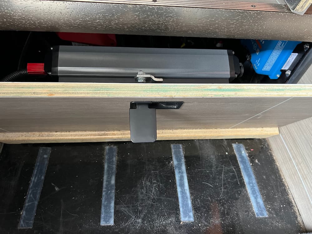
So I just mounted it on the removable door:
Whats also nice is that Renogy uses Anderson PP75 “Powerpoles” to connect, so it can be unsnapped to remove the door. Closing the door partially it looks like this:
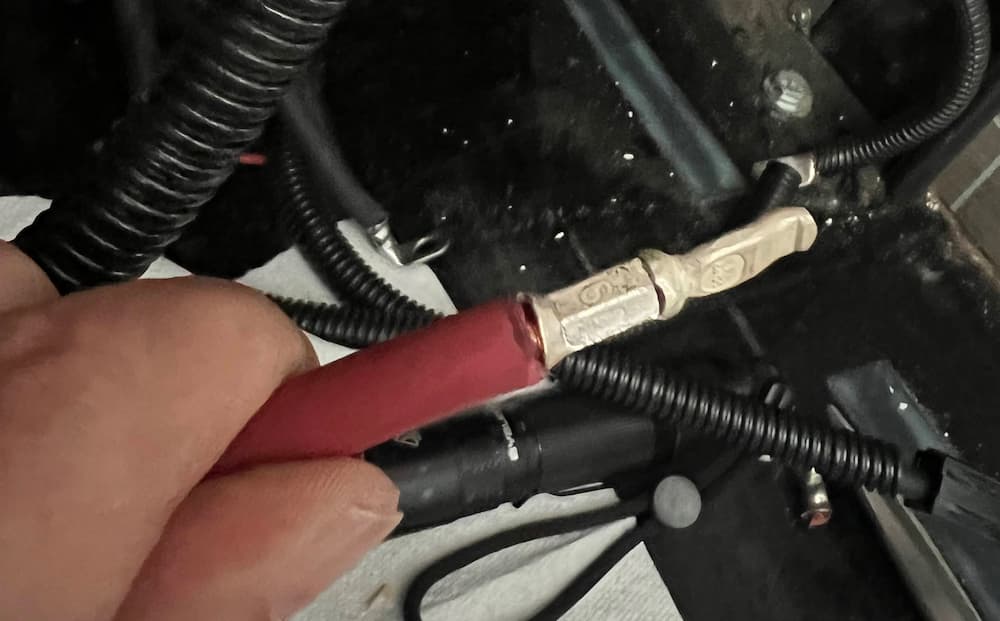
Incidentally, I think it usually comes with with a 10 foot Anderson cable, but I bought it off Amazon on a “warehouse sale” which was missing the cables. But it turns out you can buy a set of Powerpole connectors (link below) which use a standard AWG 6 crimp, so it just takes seconds to make your own:
All you do is crimp the connector and push into the housing; I love these connectors and I’m sure I can find some other uses.
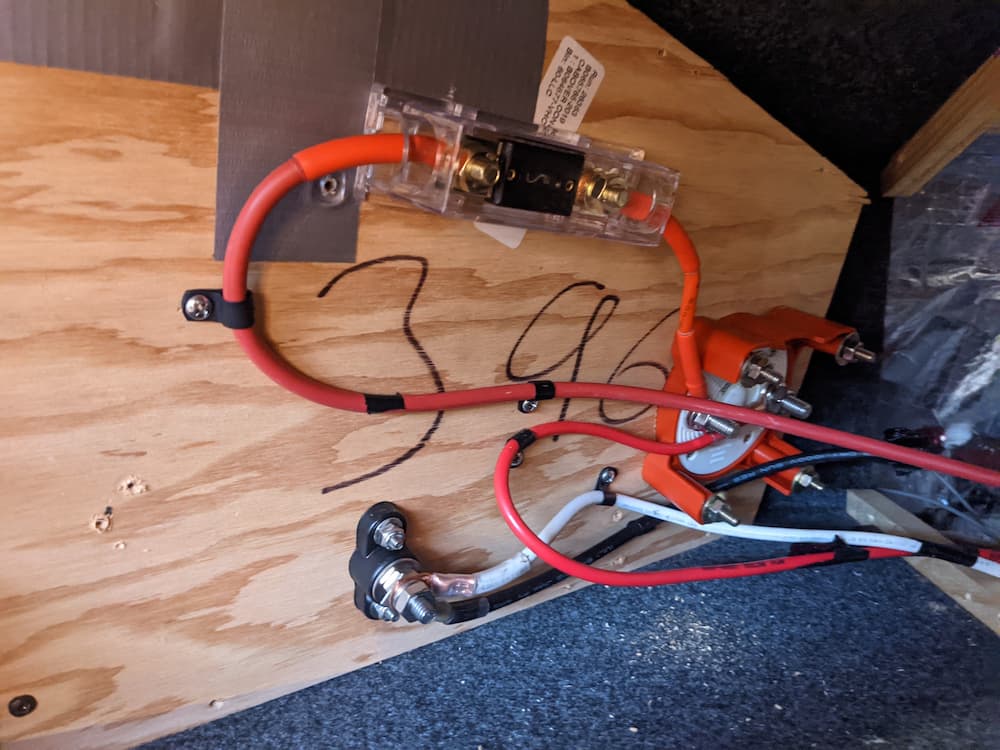
For fusing, I put a Bussman 80 amp fuse in the existing AMG/MEGA bar. This would be for the output (house) side. On the input side I use a Blue Sea 80 amp breaker. The Cole Hersee is rated for 85 amps continuous. I put a 3 amp inline fuse on the control wiring to the dash switch.
I connected the “house” side to the Rego and switched on the battery. Everything seemed to work fine. The Renogy “DC Home” app worked and I was able to access the user settings and setup the charge profile for my battery.
One thing I do not like about the app is – no security! That’s right, anybody with the app can fiddle with your charge settings. It need not be malicious – they might think they are connecting to their own battery. I plan to test the Bluetooth range and consider keeping this switched off if other RVs are within range. Thanks for being stupid, Renogy! I do hope they fix it on an update – and Renogy is known for reading their Amazon reviews, so one can hope.
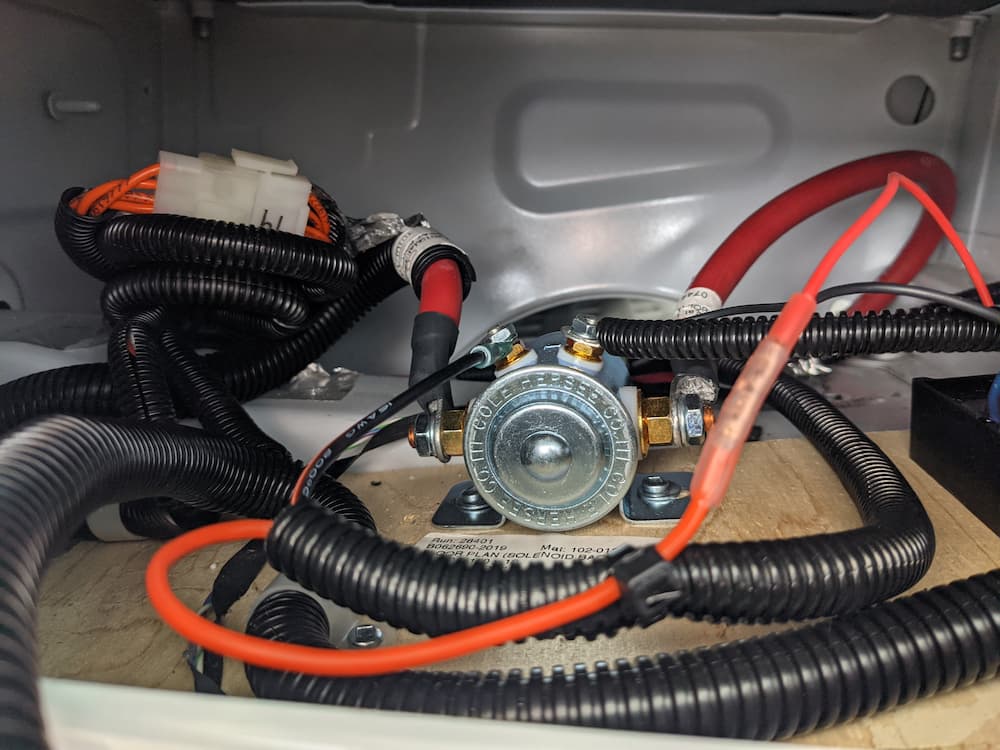
I just received the Cole Hersee solid state relay. This really is totally unnecessary. You could use a $20 relay off Amazon. Or even the battery isolator I already had under the seat. I just choose to use this thing because its so cool and has no moving parts and draws no current.
Here is the Cole Hersee wired under the seat before I screwed it down. I removed the original IRD and solenoid:
I powered everything up, and it seems to work. The dash switch connects and disconnects the starter battery, preventing the Rego from doing anything when I don’t want it to.
Displayed voltages were correct on both sides.
The relay may be overkill. You could have a manual switch, or no switch at all. Sometimes I like to overdo things.
One slightly odd artifact I have observed – if I pull the ground bolt under the gas pedal – for extended storage unpowered – as expected, the Rego will show zero on the starter battery since its “gone”. No fault codes or lights or anything.
On the other hand, if I switch off the battery master switch – but leave the Mercedes ground bolt connected – the Rego starts a fault beep with its light flashing. Maybe this is a good thing. If I am leaving the RV for a long enough time to turn off the house battery I almost certainly would want to also disconnect the Mercedes battery – so the beeping certainly prevents forgetting that.
As it stands though if for some reason thats what I really wanted I would have to throw the breaker on the chassis side of the Rego in that unlikely event to silence the beep. So not a big deal either way.
Update: Feb 2023
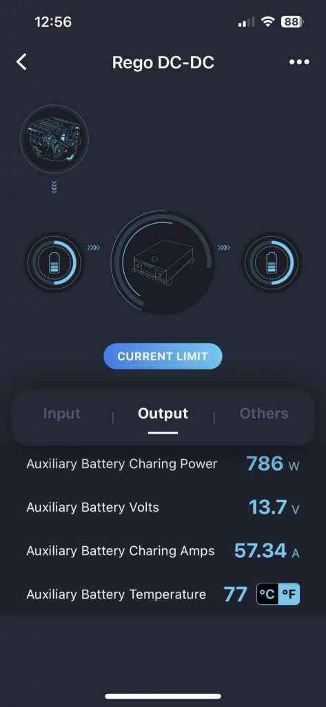
I did start the engine and let it run briefly. Sure enough pumped about 57 amps to the house battery after about 30 seconds so I’d consider this a wrap for now:
A few days later I drove the RV for about an hour. The Rego started with 60 amps charging but switched after while to 40 amps while doing a “boost” (absorption) charge. It could have stayed longer at 60 but I also had solar streaming close to 30 amps, and I think DC-DC chargers get confused in that situation and see the higher voltage as a sign its time to cut back.
So it seems fine to me! I drove home and plugged in the RV and for the first time in 4 years of ownership I didn’t have to get out a charger for the Mercedes battery. As soon as I plugged in the Rego started reverse charging the starter battery and that floated it all night.
March 2025 Update:
Well it still works and I am mostly satisfied. The Cole Hersee solid state relay sounded like a great idea but didn’t work out. Its super expensive but didn’t seem to work. I think because the input and output were not exactly the same. I removed it as it wasn’t needed anyway, and I ended up later using it on my NovaKool refrigerator install as a low idle current remote on/off switch. Total overkill for that but was just gathering dust anyway.
We travel with a backup refrigerator that is hugely useful, depending on our mood, as a wine/drink cooler, holding area while we defrost the big fridge, or, in a pinch, a second usable refrigerator in case the big one fails.
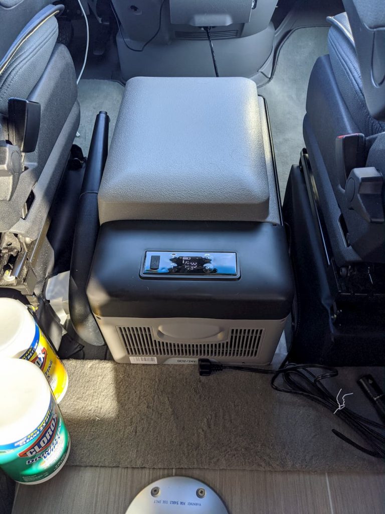
We previously had an Alpicool Refrigerator which works great and fits behind the drivers seat.
Super nice, but the thing was tiny. So last summer we upgraded to this relatively massive once that runs off a Danfoss compressor just like the big boys. You can run it as a refrigerator or a freezer (but not both).
Its relatively massive at 50 liters – in a pinch, enough to get by on for weeks without spoiling a vacation.
And yep, it still fits in the dead space behind the driver’s seat.
We used this all summer and man! was it neat. You can fill it with warm wine or drinks and they are cold before you know it. Also used it while defrosting the Isotherm.
I can’t say enough good about it. We ran it nonstop for months. Its quiet, uses just a few amps, and worked great all summer.
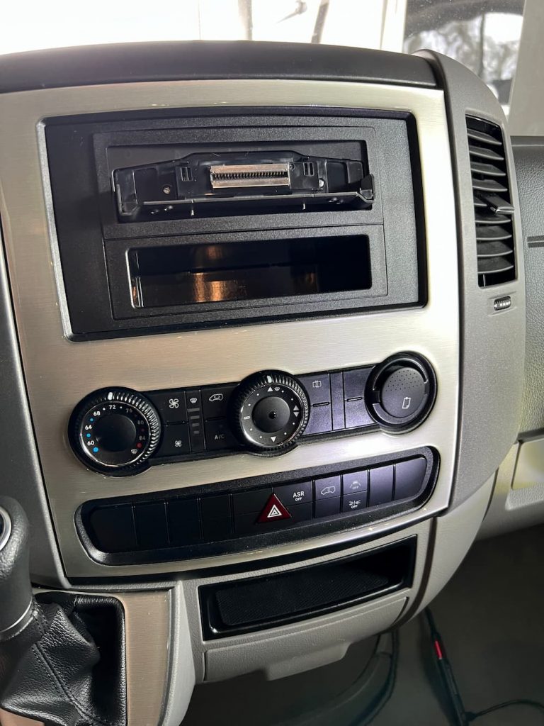
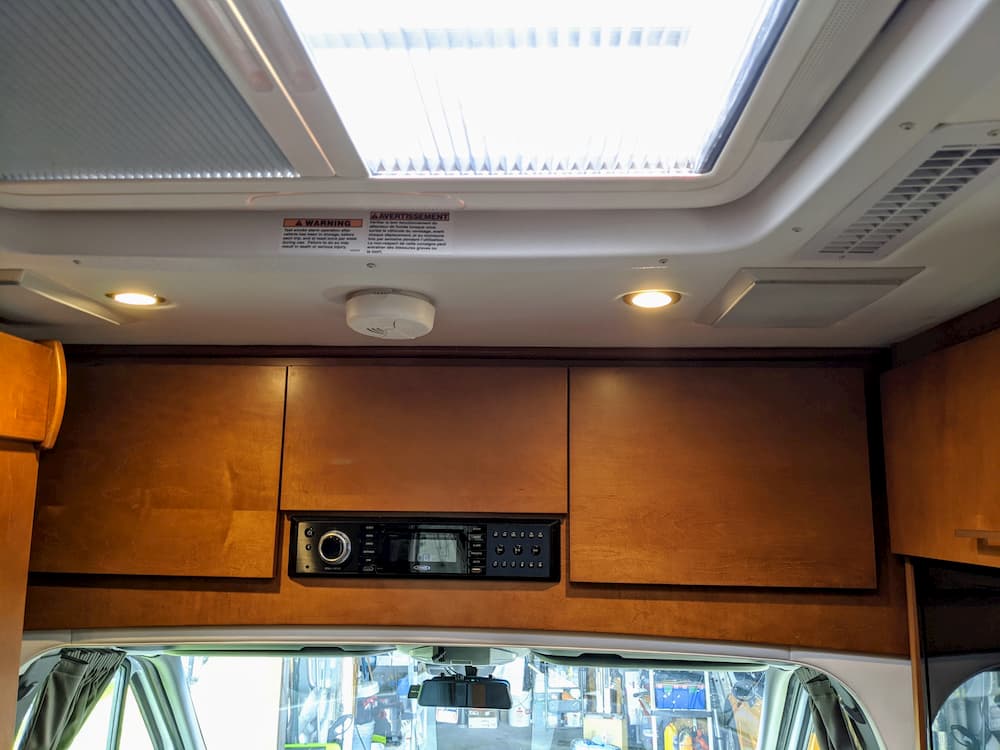
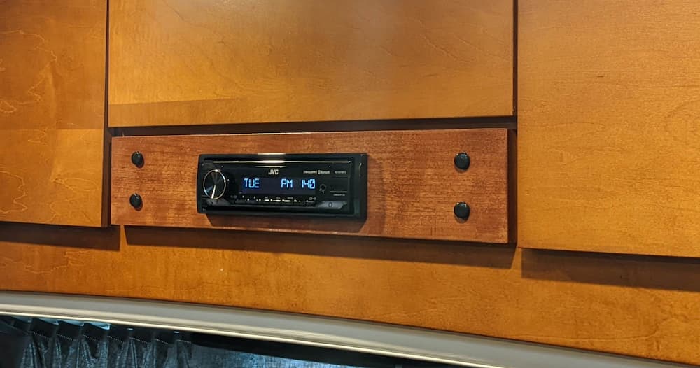
I previously had replaced my junk Sprinter radio with a Pioneer Avic-W8400NEX. This worked out pretty well. It had wireless Apple Carplay and was pretty advanced at the time. That thing was damn expensive!
After 4 years of use, I was *mostly* satisfied. But, since riding in Teslas I have grown fond of the oversized exploding video screen in the dash. I used to think it looked junky and toyish, but heh, its 2022 now.
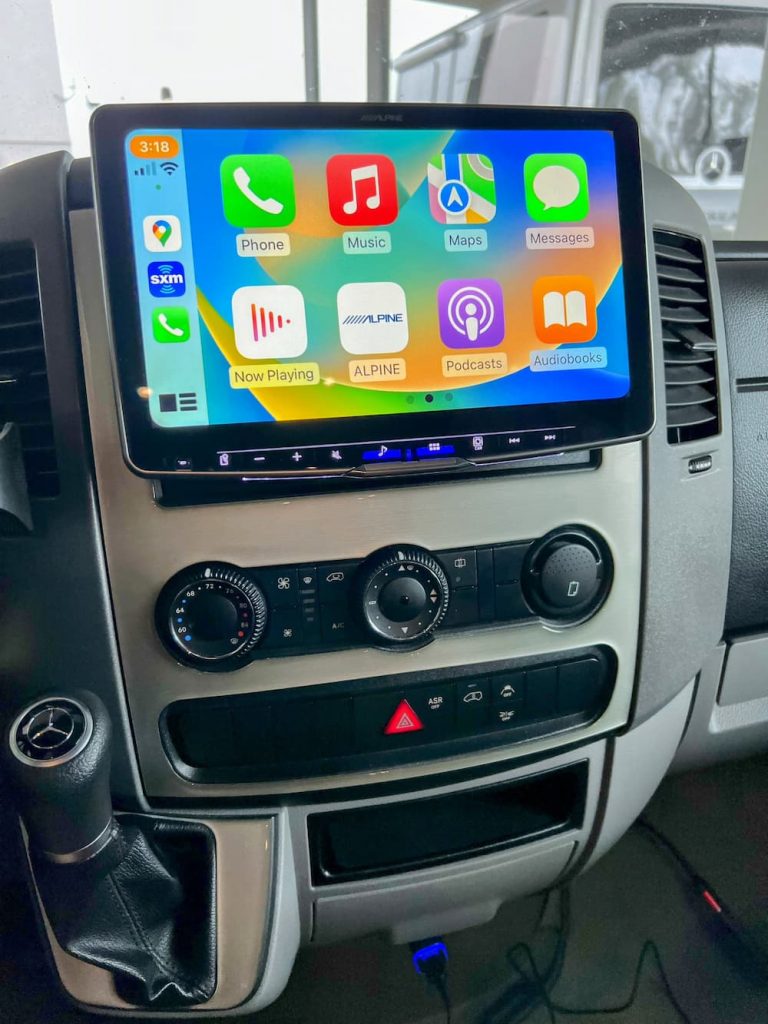
So I searched for the biggest badass radio I could find, and it looks like this is it! This monster has an 11″ screen and should help freshen the appearance of the Sprinter cab which always had a plumbing truck feel for me.
The Alpine does not have an offline navigation app, but I found that I rarely used mine anyway. Most of the time I can download Google Map routes in advance when I have cell signal, and Google Maps is WAY improved now at navigating rural areas. In rare cases I can use the offline GPS app (Sygic Truck) on my phone as last resort.
I bought from Crutchfield. Besides their good reputation they also have a wire harness service, where, for a few bucks, they crimp all the connections for you on a custom harness with a steering wheel controller making the whole thing (almost) plug and play.
I did go ahead and purchase a parking brake cheat relay, so I don’t need to engage the parking brake to use settings or pair a phone. Naturally I recommend you never do these things while in motion, but I often don’t bother with the parking brake on flat parking spots so it would have been a nuisance for me, even while stopped.
And some of the reviews indicate its truly awful. You have to engage the parking brake, sometimes twice, to do anything in settings or HDMI, and if you know Sprinters you know the parking brake is a bit finicky and a handful. When its very flat I sometimes leave it off.
So on to the install!
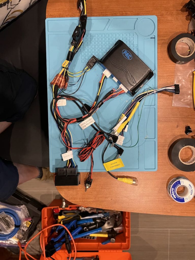
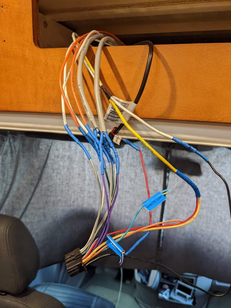
Here is the main wiring harness with my small addition of the parking brake cheat:
Just to the right of all those nice crimps Crutchfield did – you can see the relay I patched in.
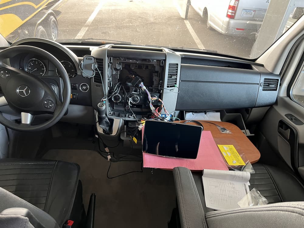
The next step is to “dry run” the installation. So using the conveniently (never used) “Captain’s Table” that came with my RV) I jury rigged everything:
I reconnected the Mercedes ground bolt and – drum roll – it booted!
However, after a few seconds it turned off. Several more attempts also failed, and I called Crutchfield, who didn’t have any idea either what could be wrong.
He did make the sensible proposal that I should start cutting apart that nice custom harness I paid for, and try hot-wiring the red and yellow to 12 volts along with the ground, to see if that got a clean startup without connecting the harness to Mercedes – as a first troubleshooting step.
Instead I decided to first try removing the parking brake cheater relay by cutting it off. That failed to solve anything.
Sometime during this frustration I discovered the answer – which I already knew but had forgotten. In tiny print in the manual is the statement that you must connect the “power plate” a small piece of plastic – or the display won’t turn on.
Since this was just a preliminary test I had forgotten that step, and in any case, the manual implies that the display won’t power on – NOT that the Alpine will enter a one time Boot Loop.
(Later I found numerous Youtube videos of other installers suffering the same woe)
So after connecting the power plate and reinstalling the parking brake cheat it worked perfectly at last.
At this point the unit seemed (mostly) functional. I also plugged in the Sirius module and confirmed that worked.
Note that Mercedes has a few “FAKRA” connectors that Crutchfield included in the package that I purchased – however I already had these from my previous Pioneer installation.
They are:
Green FAKRA to yellow camera input
Black FAKRA to radio antenna
Violet fakra to Apple CarPlay/Android Auto USB
Before I get too excited, the next step is to locate the GPS and Microphone.
You might ask yourself – since this unit has no mapping software, why does it need a GPS? Well it turns out with wireless CarPlay/Auto its required. Reason is, the phone may be buried in your purse or glove box with poor GPS reception.
And even with wired Carplay, your phone may be kicking around somewhere and not give the best location – so don’t skip this step.
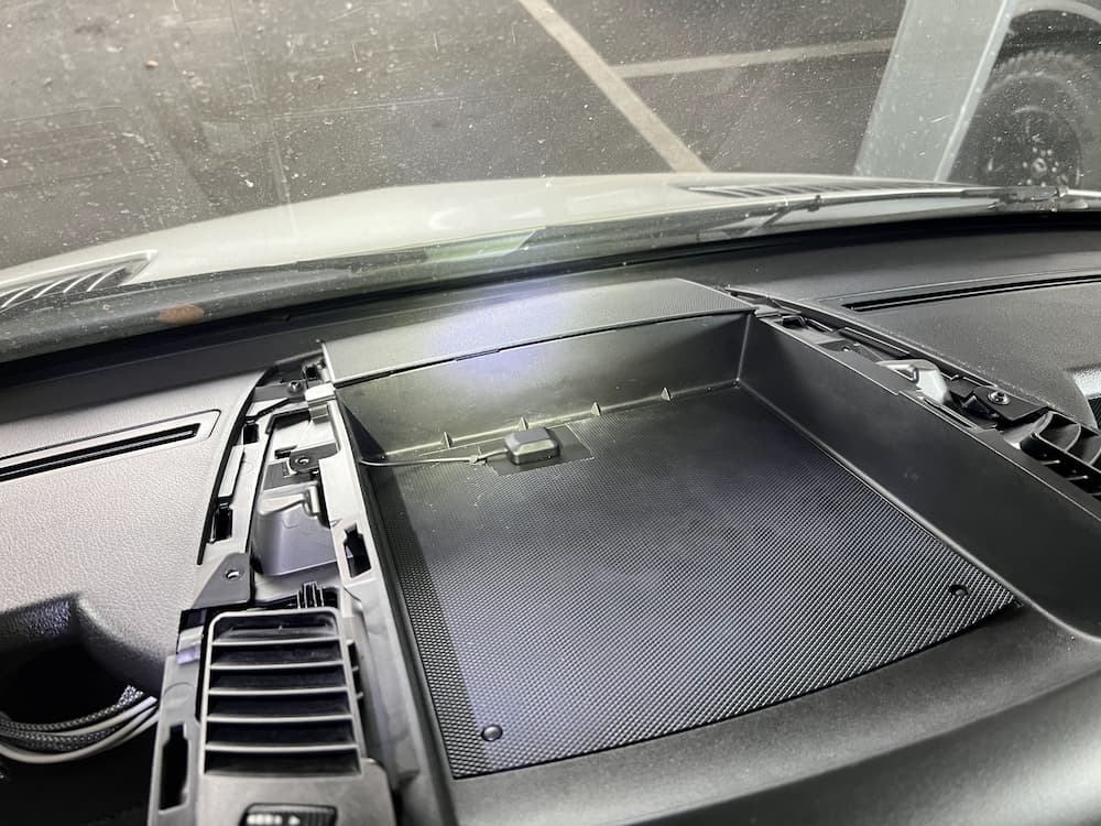
You don’t need to locate the GPS on top of the dash, but it should be close. So I put mine above the radio in the tray:
This is covered later with the plastic top so the GPS is not visible, but only a thin skin away from the stars.
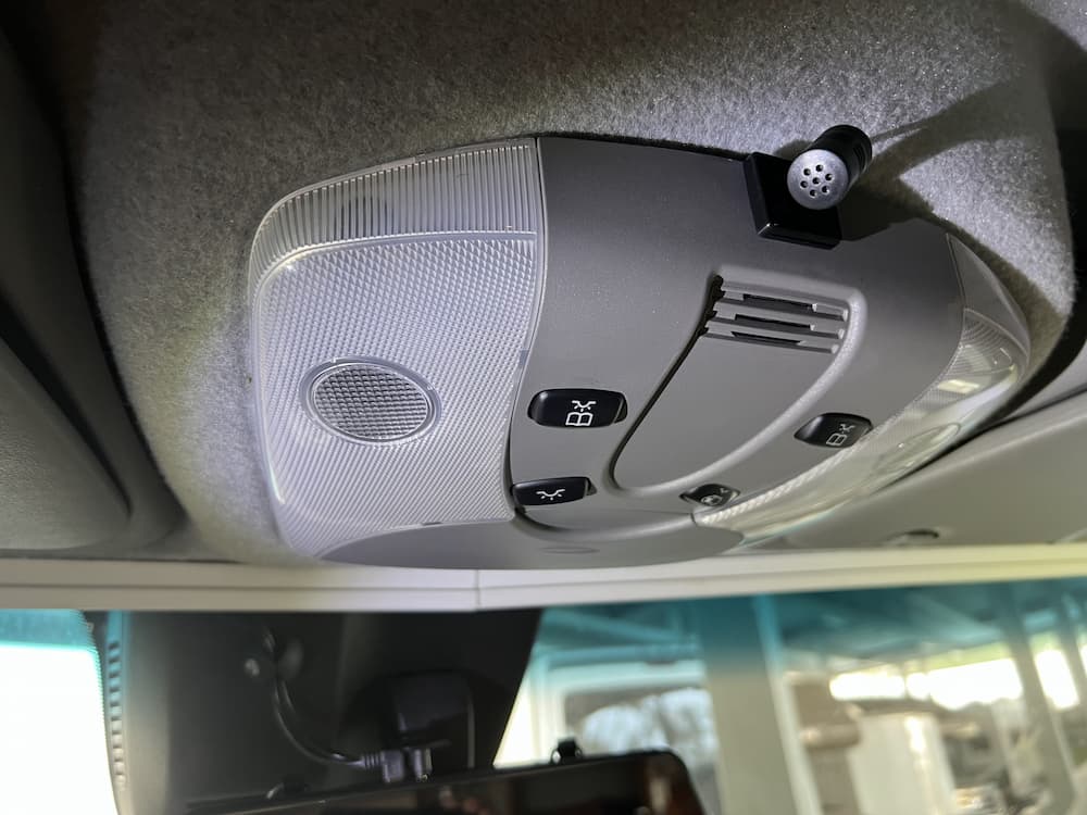
The microphone I located overhead:
This looks like a chore, but is quite easy. The “A” pillar that runs from the dash to ceiling on each side pops off easily and you just fish the wire to the overhead console which likewise drops with a squeeze.
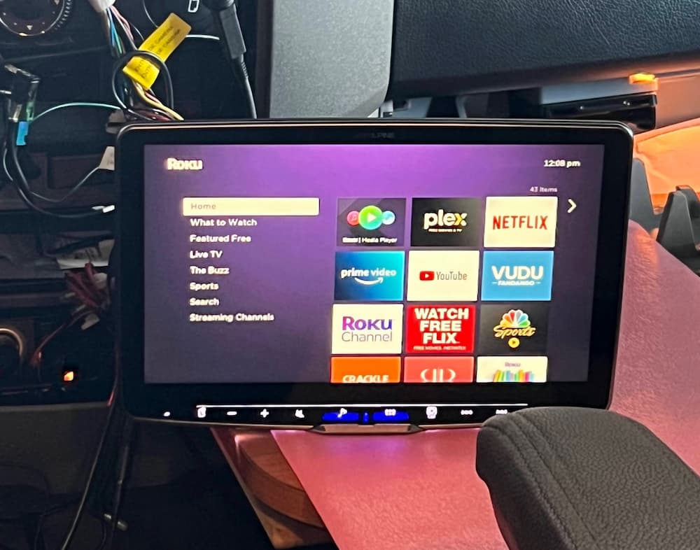
Lastly I also connected a Roku stick to the HDMI port. While it sounds like suicide to watch a movie while driving, and I’m not sure I’ll ever use it, I couldn’t help myself.
OK, so it would be seriously insane and possibly get you nominated for a posthumous Darwin Award to watch TV while driving, but I can see this being occasionally useful, say, while at a rest stop or dumping.
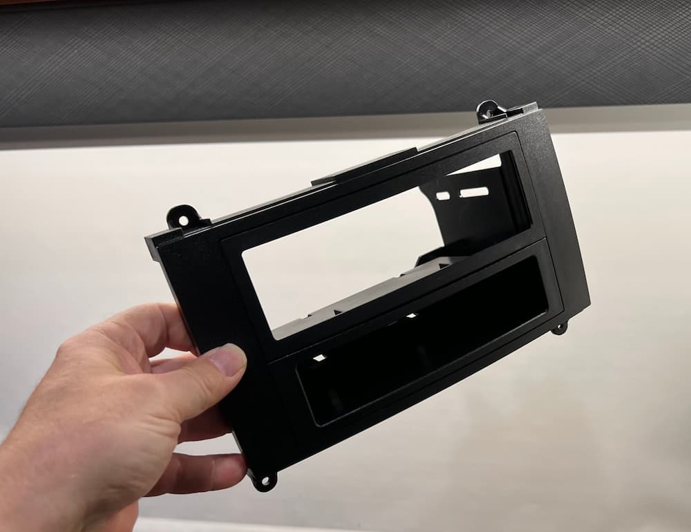
The next step was to see about actually mounting the beast. The single DIN Mercedes adapter seemed really flimsy but after it was screwed together seems adequate:
A little dark to see in the picture but the bottom is a nice pocket. Since I plan to slide the screen down it will probably be unusable though.
Here is a pic of the single din Alpine mounted. Very easy since I left the display off for now.
Finally I added the display. The display angle is adjustable only when mounted, so be sure to do a “dry run” mount first before its in the dash. Then straighten out the display to nearly vertical.
Later, when you finally mount it, you can angle it away slightly if necessary to mount the rear cover plate.
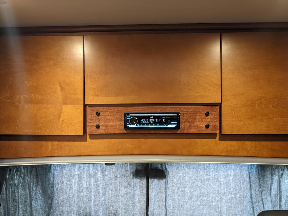
Once that was all done, it looks gorgeous:
Note that I mounted the display as low as possible, for a more stealthy look and also to avoid baking the display in the sun. As a result of this the pocket under the radio is almost totally covered. You could adjust the display to be higher if you want to use the pocket.
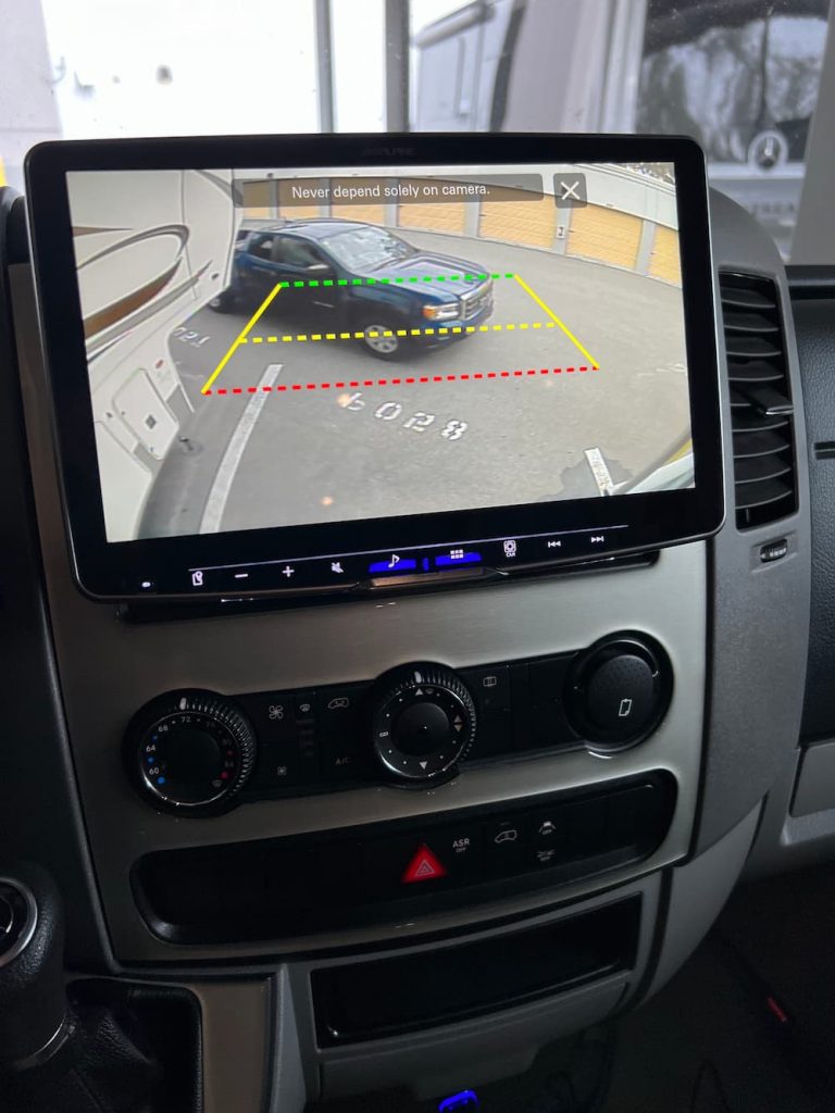
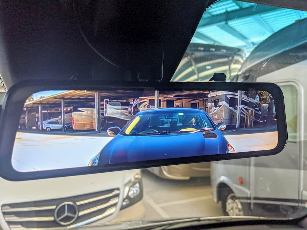
Everything works perfectly – steering wheel controls, my aftermarket Sirius XM, Roku, and the factory backup camera. There are alignment guides I can adjust later:
This was actually a pretty easy install, thanks to Crutchfield, who not only made the wire harness but also provided great technical support on the first ring when I had a couple questions.
On a scale of 1-10 I would rate this a 6 in difficulty. Not hard it all if you are patient and read the manual. And thanks to Crutchfield, it was plug and play except for the parking brake cheat.
Update: Well, these were great batteries, but I did yet another battery upgrade to a pair of Epoch 300 Essentials. The Epoch fit in the same space and gave me 50% more amp hours, so I couldn’t resist.
This will be my third Lithium upgrade in the same van. I’m unwilling to sacrifice any more space or weight, so I do upgrades as technology improves. First it was (2) Battleborn’s, then (3) Renogy. All performed fabulously (some Renogy hiccups were just rough software and resolved themselves after cell balancing), and met my expectations, until I began to see a pathway towards more juice.
Over the past year I’ve been watching a couple smaller 200 AH batteries. (I need more than one battery for travels so far from home – as a battery failure would otherwise be catastrophic – and I can’t fit two 300s.)
One is the new 200 AH Victron. Its 44 lbs, about the size of a 100 AH battery, only taller. You might reasonably be able to get two into the battery box. But I already have a lot of stuff in the battery box, and the Victron requires an external BMS that takes up space also.
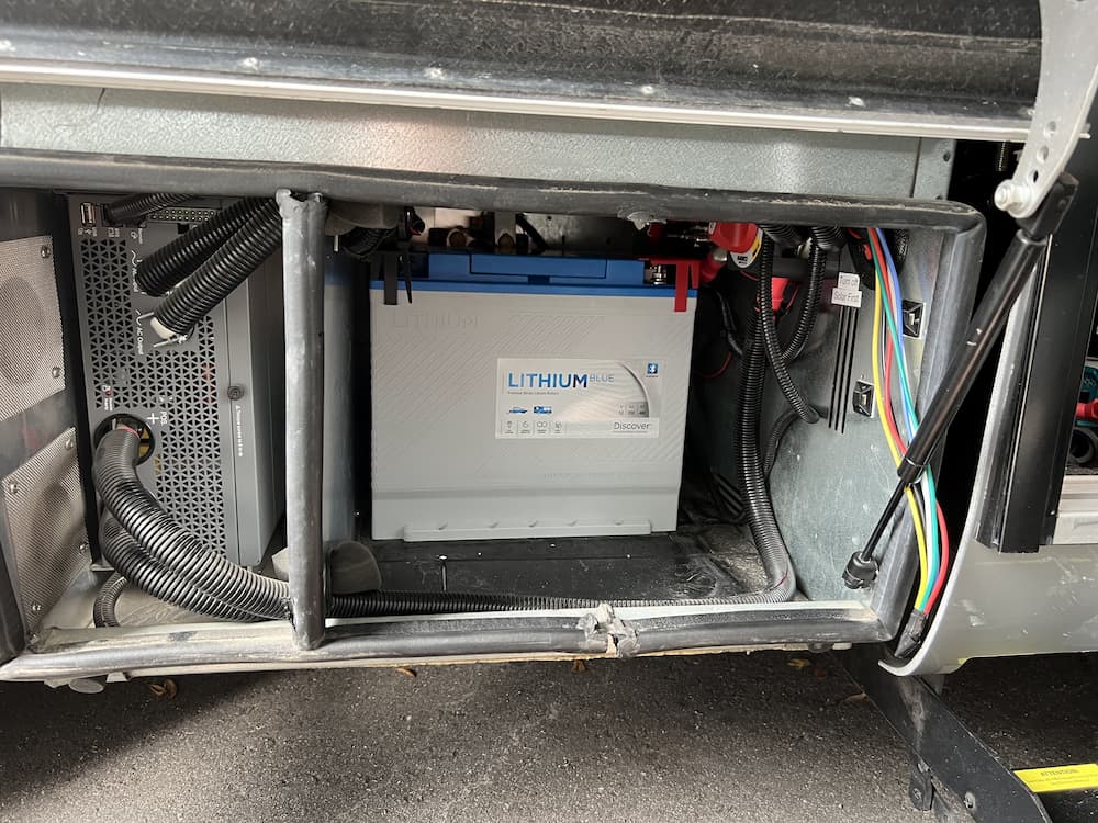
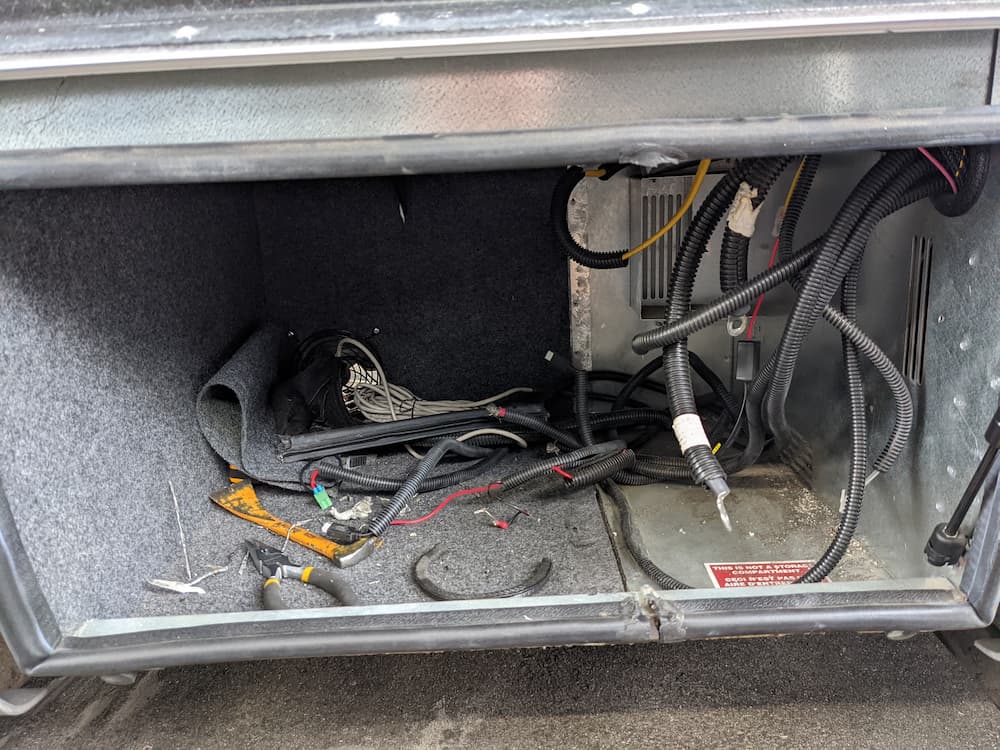
So I am planning to mount 2 batteries next to the inverter instead, which frees up the battery box for DC-DC chargers, solar charger, breakers, etc.
The Smart 200 Victron external BMS is a mixed bag in my opinion. Its pretty cool and eliminates the DC-DC charger (allows direct connect), but its a single point of failure. It has to talk to the Xantrex charger using the “ignition” line so it can ask the Xantrex to turn off charge (or load) if needed. After a lot of research I determined this will definitely work, but I’m not sure I have enough faith in Xantrex that I trust it not to destroy the batteries by not honoring the ignition signal someday.
Also a failing battery will turn off the charge (and load) for both, so I decided the external bms is not worth it for me.
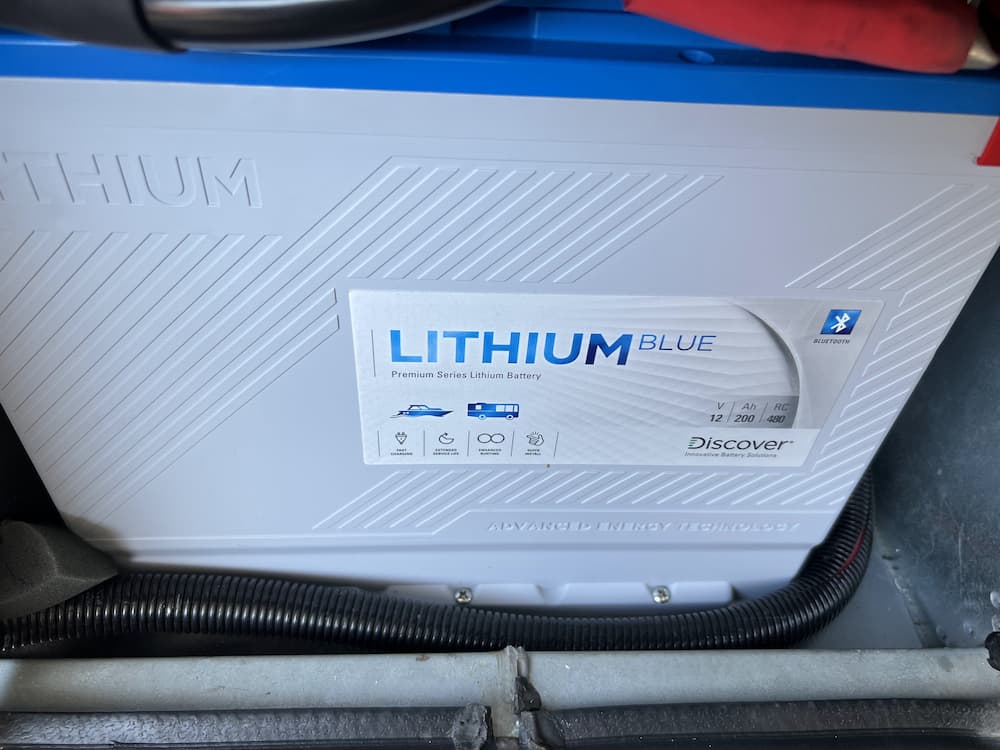
The next entrant was Discover Battery “DLB-GC12-12V Lithium Blue 12V 200Ah Battery With BMS & Bluetooth”. This is also about the size of a 100 AH battery, only taller. (Although technically two may still barely fit in the battery box, its recommended to have ventilation above, so likewise I will put them next to the inverter)
Discover is a huge, old battery manufacturer. In fact they are the OEM supplier to LTV for AGM batteries still I think. This is the Discover Battery.
It has some cool features including a field replaceable BMS, integrated handle and built in battery terminal covers. Also the Bluetooth App that is just a about a requirement now if you want multiple batteries. All in 44 lbs. Its obvious they did a lot of research before entering the market.
It is 12.2 (L) X 7 (W) X 10.9 (H). So 2 should fit easily next to my Xantrex 3000 and free the battery compartment for some other toys.
I went back and forth between the Victron and the Discover many times, until a random search found this Discovery Discover Battery Sale. (Presumably by the time you read this it may be over)
This “overstock” sale is way lower than I have ever seen these and caused the left side of my brain to immediately pull the plug and order two. Price is not a determining factor for this upgrade at all, but it sure is nice to get 400 amp hours for $2398 plus tax, all from an “old school” north american manufacturer.
My expansion in capacity is “only” 100 AH (from 300 to 400), but we just finished a 2 month trip and there were times that extra 100 would have made a difference.
So they should be arriving as soon as they can ship them, and it will be another fun project to get these installed and see how they work out… (More to come!)
Oct 21 2022
Received the two batteries today. Very nice build and the size is amazing – for perspective, one of my current Renogy 100 AH batteries in front of the 2 Discover 200 AH batteries. Discover is taller but otherwise occupying the same space although twice the capacity each. Amazing how much power is packed in these for the size!
Bluetooth app worked perfectly and I started a charge on the first one so I can fully charge before connecting in parallel. It will be a little bit before I get a chance to mount these in my van but I’m very impressed so far at least. Registered for their 5 year warranty. The warranty is a bit unusual in that they actually warrant a specific capacity in kwh. If the battery drops below that they will replace it.
I am thinking these are going to be keepers as its hard to imagine getting more than 400 AH in this package size anytime soon…
So the next step was to charge them up fully before connecting in parallel, also to inspect the cell balancing and performance. These are going to be some work to install so I certainly want to be sure they really are keepers before getting them mounted.
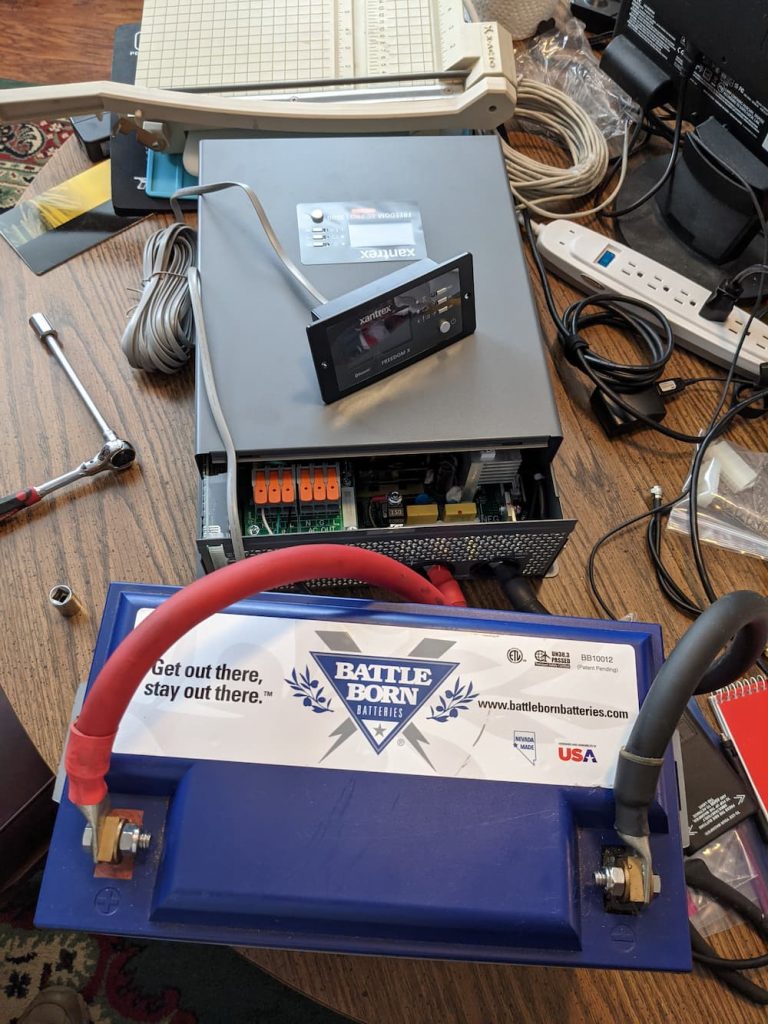
I hooked up one battery at a time to my Old Magnum 1000 watt inverter to drive a heat gun on low. That will use about 75 amps which is perfect for a capacity test. Unfortunately I used a bunch of spare cables laying around from old projects, which, together with my fully trashed conference table, produced this mess of a deathtrap:
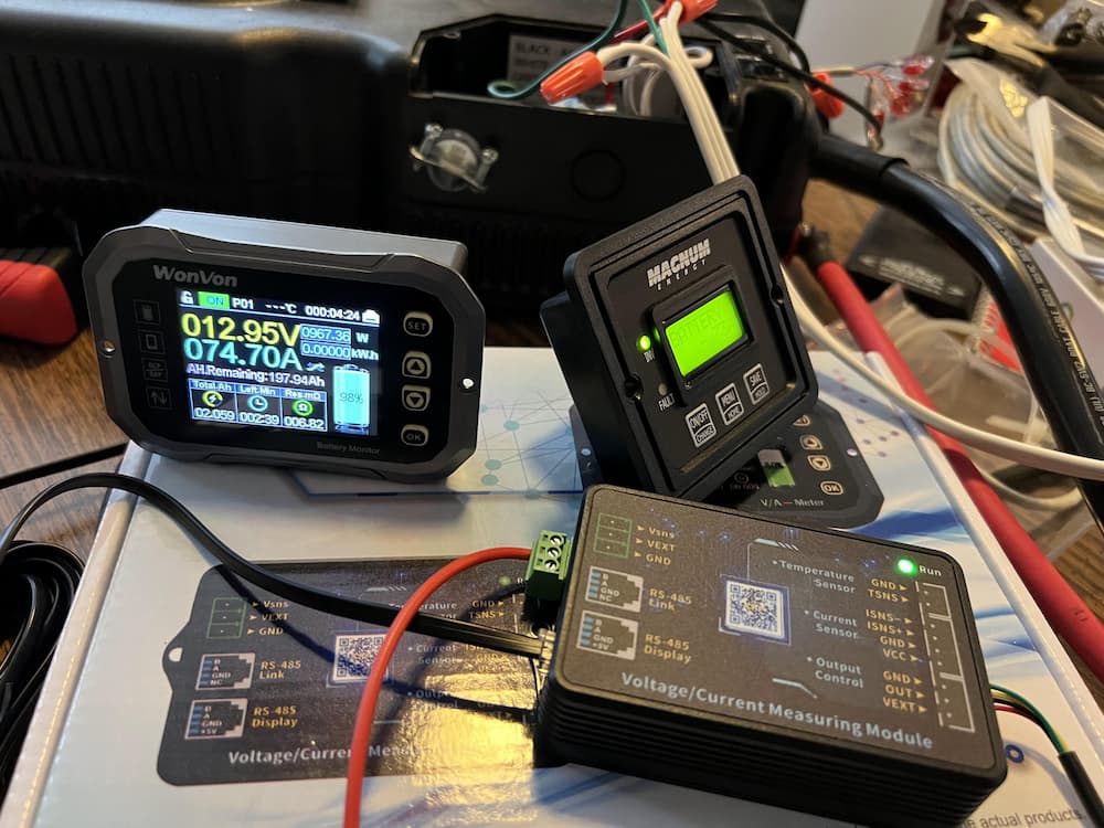
But it works! A cheap Amazon battery monitor and a 100 amp breaker completed the rats nest of wiring. Zooming in on the “WonVon” battery monitor:
The WonVon was pretty cheap on Amazon and I didn’t want to buy A Victron shunt just for my workbench. But it actually worked out real nice. It has a Bluetooth interface so I could change settings and monitor across the room. It has the usual accumulated watts and state-of-charge displays.
So on to the testing and balancing!
October 28 2022
And… The results are in:
So this is the WonVon monitor after around 2 1/2 hours of testing with the heat gun. I used up just over 192 amp hours of the battery leaving just 3% of its advertised capacity. I didn’t want to run it down to zero as, even though its OK once in a while (The BMS shuts down at 10 volts to protect the cells), its not ideal for cell life.
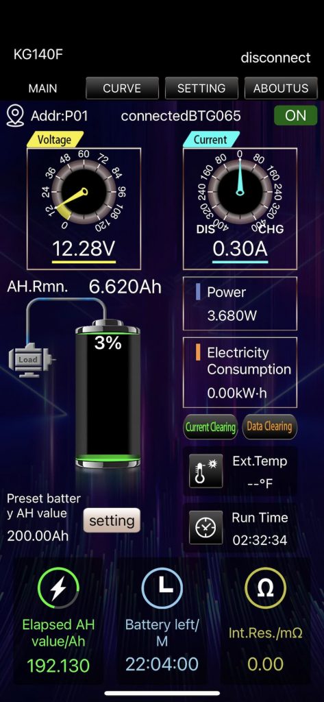
So far so good, but the Discover Battery Monitor is interesting:
This is immediately after I shut off the heat gun and turned the inverter off. As you can see it shows a higher reserve (7%) than there should be (3-4%). I forgot to screenshot it but the individual cells were at pretty high voltages – over 3 volts each – which represent an actual state of charge more like 10%.
So the bottom line is I feel pretty good about this battery. I think had I continued the test to scrape out those last few amps the actual usable capacity is going to be somewhat over the advertised capacity.
I’ll test the other battery later to be sure but so far these are very, very nice and will give me 400+ amp hours in quite a compact package.
October 30 2022
Well something to think about… the cool snap on terminal covers… might not always be 100% cool. With a “normal” battery the terminals are above the battery. Exposed, yes, but easy to route stiff 2/0 cables to. In my tight space, it may be difficult to route a battery cable to these Discovers.
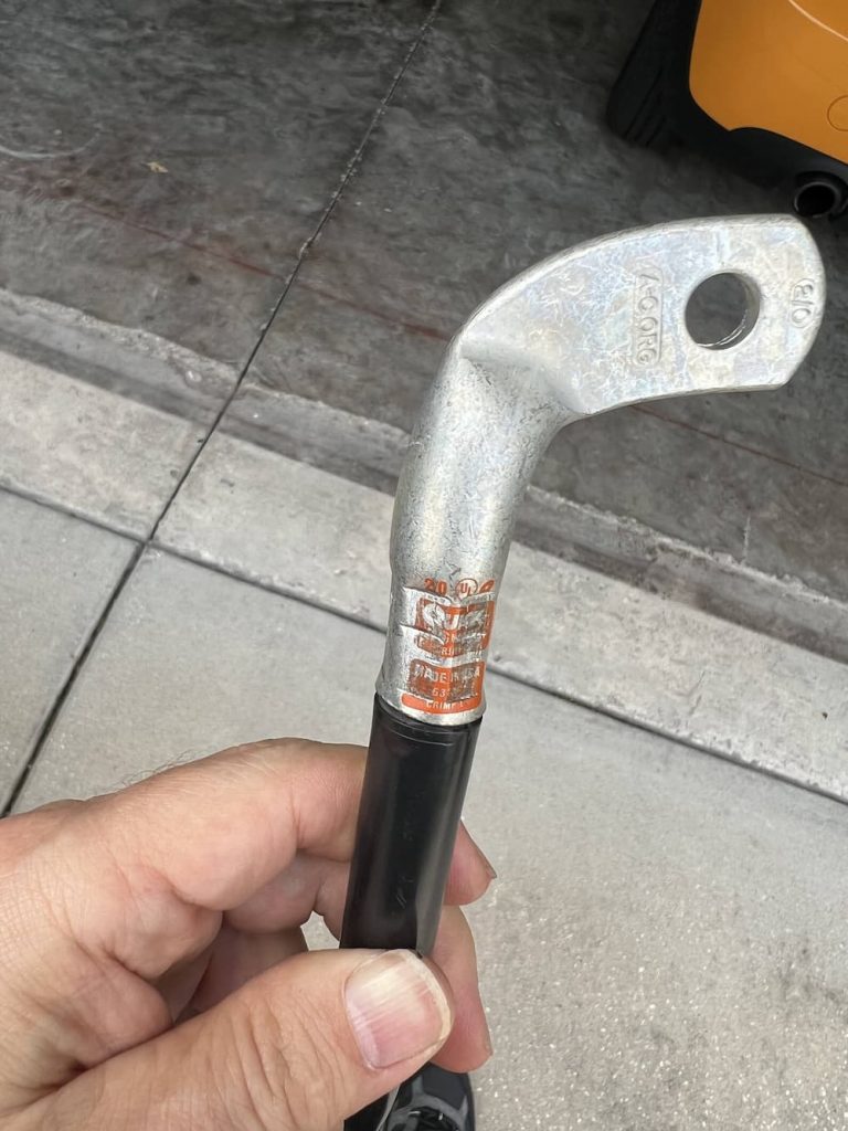
I started looking at right angle lugs, which I have used before, but the traditional Ancor ones would have the cable pointing towards the ceiling, which would still leave a tight radius for a turn.
And then I found these Elbow Magna Lugs. (the link is for the right, of course they also sell a left). I immediately ordered a few of each. These *may* fit perfectly and make it easier to slide the battery into a confined space…
November 28 2022
As I suspected the unusual terminals on these batteries, while cute, caused a little extra brain cells to get used up. I ended up ordering and trying a variety of methods to use these in tight spaces. I tried 45 degree lugs, a Tesla bus bar, and various other solutions.
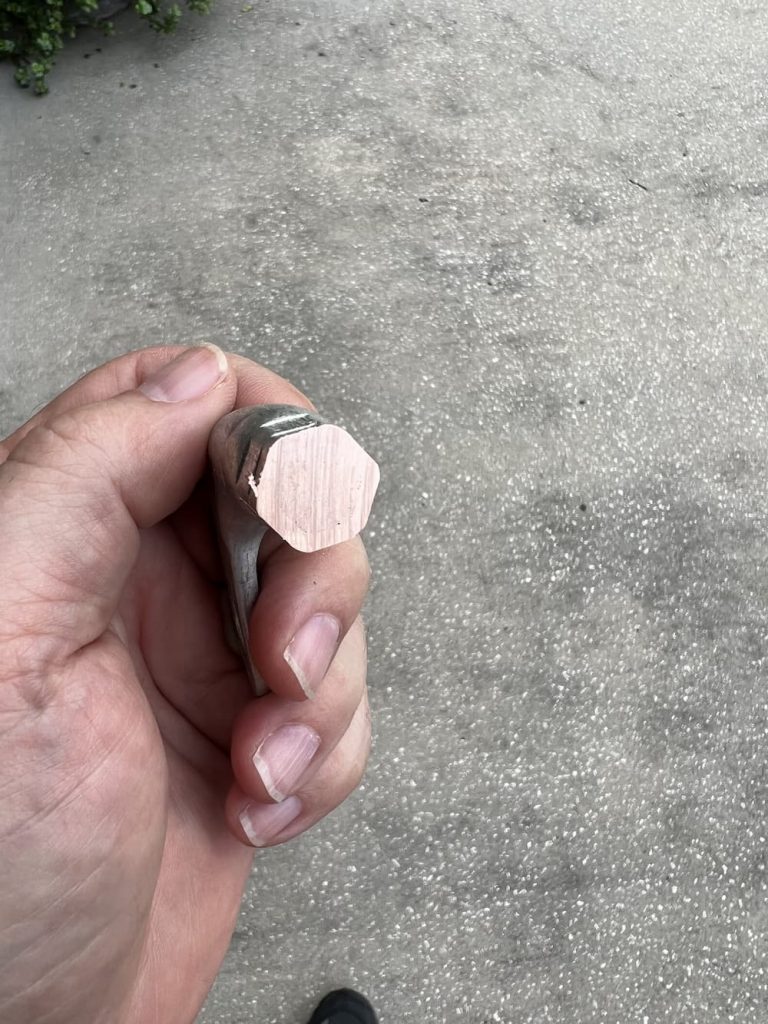
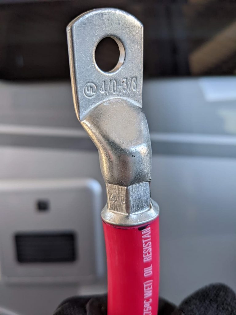
In the end Quick Cable Elbow Lugs (link just above) worked the best. These are truly massive lugs that are far thicker than anything I’ve ever seen. As a result a 2/0 die wouldn’t work on my crimper, or even a 3/0. On the third try I used a 4/0 die, which resulted in a pretty crimp.
It seemed a little too easy though so I sawed the test lug in half to inspect:
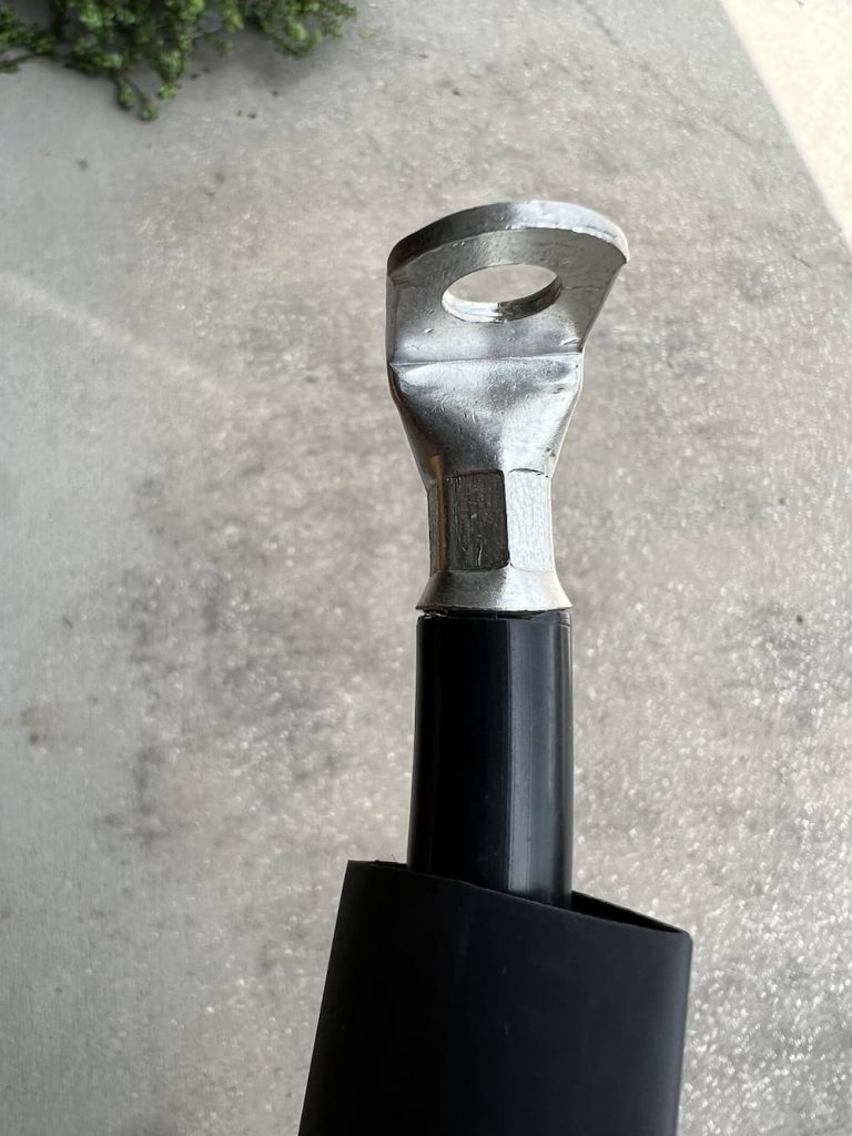
It looks good. Its shiny and has the qualities of solid copper with no spaces so I’m satisfied the crimps are good to use. Also on this huge lug there is space for 2 (slightly overlapping) crimps:
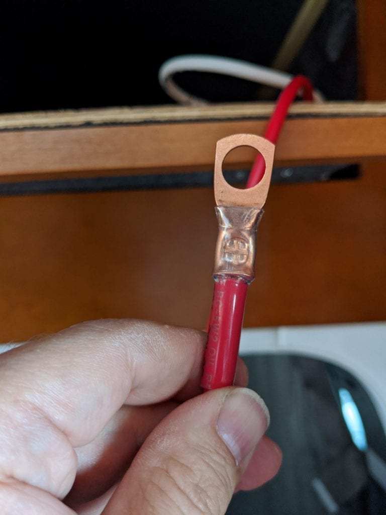
So this is the end that will go on the battery terminals and get the cable outside the lug recess. The other side of the cable gets an Ancor 90 degree lug that will go to the bus bars:
So now I just have to finish the 4 sets of cables and then try to slide these big boys in. I already test fit the first battery:
The first battery fits easily, and there is enough room for another. But I do have concerns that sliding in the second one is going to be tricky! Guess I will find out shortly.
December 1, 2022
Well this was a lot easier than I would have thought! The Unity Corner Bed Inverter compartment is WAY smaller than some other models (like Murphy Bed). (In case you are wondering, I installed my 3000 watt inverter on the opposite side of the usual configuration).
Still, the second battery slid right in – no problem. Because I took the time to find the right elbow lugs everything fits perfectly and they were literally just minutes to mount.
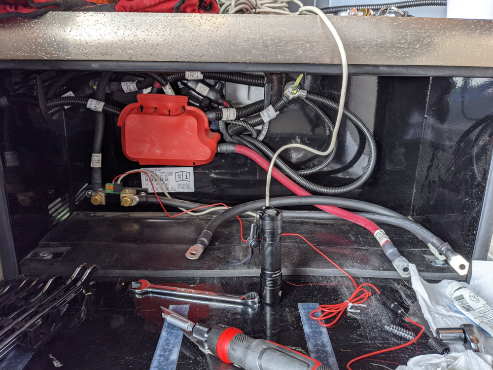
Here is the empty compartment, after I mounted the cables:
I used a Marinco dual switch and link bars, Class T fuse, etc – all connected together in the upper right. This configuration allows one switch to isolate the batteries AND switch the inverter on and off. I detailed the advantages and parts needed in a previous install.
The rear wall has a Blue Seas busbar for the battery negatives and a Victron BMV-712 Battery Monitor.
The two batteries easily slide right in. There is enough room to torque the positive terminals first for safety.
There is plenty of room on the sides and top. One of the super cool little things about these batteries are the built in mounting screws:
This allows a really quick and tidy installation – no ugly straps or messy hold down blocks. I could only easy reach the front screws but they are still very firmly attached.
I threw the Marinco Switch, and satisfyingly, no magic smoke!
These batteries are very impressive so far. A five year warranty, old and established North American manufacturer and far denser and smaller than almost anything on the market, all at a very reasonable price. I’ll make a final update to this post once we get a chance to make our first short run with them!
The wiring I used was Ancor Marine wire. I’ve also listed many of the parts and tools below that I purchased before this install.
Dec 30 2022
Hadn’t had much of any chance to use the batteries camping but I do have some follow up observations having installed them a month ago. My RV is stored under a roof at a nearby storage facility with no power and near zero solar, so most of the time I keep my master battery disconnect off.
I’ve been doing some projects in the RV here and there, utilizing the batteries and sometimes the inverter, running heat guns and other high amp appliances and then occasionally recharging on the generator (set to 150 amps charge).
One thing that bothered me at first is that they never seem to enter sleep mode. Most Bluetooth batteries (including these) are supposed to turn off fully in 24 hours or so, and be awakened by small currents of an amp or whatever. That’s how my Renogy batteries behaved. You could tell they were sleeping because the Bluetooth was disabled and the voltage was like 6 volts or so across the terminals.
My Discover batteries never sleep regardless of what the documentation says. I can use the Bluetooth anytime, and they always have full voltage. I’m theorizing that connecting them in parallel may prevent sleeping, but I recall both batteries arrived from Fedex fully awake in the box.
The concern would be that during protracted storage the failure to sleep would cause the charge to diminish, but it doesn’t seem to be the case.
Whatever is going on inside the battery is of such low voltage draw that I can’t practically measure any drop, even some weeks later, so it doesn’t seem to be a concern for storage. Maybe over 9 months it would accumulate, but we never store that long, and its recommended to charge them every 6 months anyway.
The second thing I’ve noticed is just how ample the capacity of the BMS is compared to some batteries. With 2 in parallel they are rated for continuous charge or discharge of 300 amps (150 each). And 500 amps for 2 seconds.
I use 150 amps nominally with the AC running (typically much less as I have solar), so I have measured them running it about 50% of continuous capacity maximum while using the highest possible inverter loads. Beware of el-cheapo Amazon batteries with much smaller ampacity bms (like a 200 ah battery with a 100 amp bms) if you are considering running high amperage loads.
For the size and weight you are not going to find a better solution, not counting the super-low price. There was a FB post that somebody put two under their step, which personally I wouldn’t do because of the difficulty in installing and removing. I like the more spacious area next to the inverter. (And these batteries recommend a good air gap above due to the top mounted bms.)
So after a couple of charge-discharge cycles I think I have finally found my forever batteries. Although, I keep eyeballing my partially empty step location now as I could easily squeeze a third 200 amps battery in there…
Feb 2023 Update:
Still too busy to use the RV! But one of the batteries has failed! Actually the battery still works fine, but the Bluetooth failed on it. I can tell its still working because the good battery is reporting 1/2 the load the Victron battery monitor does.
I reached out to NAZ Solar Electric who gave me the link for Discover Battery support in Vancouver. Discover Battery has been around since 1949 (unlike a lot of popup Lithium battery assemblers) so I am hopeful the warranty service will be a pleasant experience.
Since this battery has a replaceable BMS (the top is removable) they should be able to send me a new top. Unlike just about any battery made today I will not have to return the entire battery!
So while Im sorry this happened, it will be a great opportunity to document how Discover responds and the process for replacing the BMS myself.
…
Well, a day later the Bluetooth turned back on. So for now this looks like a glitch, not a failure. Maybe there is a watchdog timer in the battery that resets the Bluetooth daily or something. I’m still waiting to see what Discover says on my ticket, even though I may not ask for a replacement anymore.
May 22 2023
Just a postscript. Discover offered to send a new BMS but I declined as the glitch never repeated itself. I have used them a couple weeks now and the batteries seems to work great and deliver as advertised, so I am still very happy with these!
Nov 2024 Update – The Starlink Gen 2 was great but I since purchased and installed a Starlink Mini on my roof.
I’ll admit I was initially a Starlink skeptic for RV usage. Its heavy, big, uses a lot of current, and until recently can’t be used in motion. (While you might be able to use in motion now, you would have to heavily modify the dish to lay it flat).
That said, we realized that every year we cut our RV trips short because of lack of Internet. My job requires me to be in touch for emergencies, and so most of the time we have been leaving wilderness areas after short visits because I can’t take the risk of staying out of contact.
So this will be a life changer for me. It means we can camp anywhere in the US and have some Internet. (Even with a lot of tree cover, I usually get something, and the 75 foot cable means you can station the dish pretty far in a pinch.)
For us it was worth spending any amount of money and time to make this thing work, as it means the difference between traveling or not. We prefer camping in remote and wilderness areas, and more times then not there is not usable cell Internet service.
For starters I already have excellent Verizon and AT&T Internet in the RV. Much of the time, while driving or in civilization, that will still be the Internet carrier. Starlink takes some work and up to 30 minutes to deploy, so it isn’t going to be the first choice for Internet when other methods are available.
So I started with an excellent Pepwave cell Internet router. With its dual carriers a lot of the time I’ll have premium Internet while traveling.
Next, I did a “dry run” of Starlink. This entailed just using it out of the box, as is. Setup was 15 minutes and done. I mounted the dish on the ladder where its high and safe (but can still be ground mounted to avoid trees as needed).
The Starlink router I just dropped in an outside storage compartment. There is enough play in the rubber seals to run the power and dish cables in and still be able to close the door, and the outside outlet is powered by the inverter or shore power. I detailed that simple 15 minute Starlink setup.
However there were a couple of improvements I wanted to make!
The next step was to cut the Starlink dish cable and install RJ45 jacks and plugs. It turns out its fairly easy and fun. I wrote up those details at Cutting Starlink cable and installing RJ45 Plugs.
By itself that didn’t yield anything, but it enabled the next step: installing an outside Starlink jack:
Looking closer:
As an aside I really should remember to clean stuff off before I take pictures, instead of shooting them while the dust is still settling! In this case drilling a good sized hole through the RV panel sent dust everywhere.
The dirtiest part of the job was next. I bought a spool of Cat 6a cable off Amazon (links below) and ran a network cable under the RV, terminating the other end above the TV. To accomplish this I located the cover plate Triple E installed (Thanks Sprinter Forum!).
Its found just forward of the door on my RV, and inconveniently, on top of the Equalizer Systems pump. It was just barely reachable with some grunting and swearing. And it took some good prying and yelling for it to come loose:
This photo is after I drilled a couple holes in it for power and network wires. (In all honesty, the hole on the right turned out to be badly placed and I had to plug and move the hole south, but thats another story)
The reason for 2 holes is that I also ran 3 #10 wires up; more on that later.
So the network cable goes under the RV all the way to just forward of the door, then up through the wire valley thoughtfully provided by Triple E, then behind the right shelf off the passenger seat (just unscrew the side panel to pull it), and then finally above the TV in the entertainment cabinet:
I’ll admit a few times during this job as it stretched into a couple days I questioned if it makes sense or was even going to work, but I really want to see more of the US and Starlink is my ticket!
The REALLY nice thing about running RJ45 jack to RJ45 jack this way is you can use a $10 network cable tester off Amazon to make sure you wired it correctly, link below.
At this point, I put the router in the entertainment compartment, plugged it into the jack above, and, mission accomplished! I now can easily keep my router inside, and simply deploy the dish outside when needed with the jack I installed.
Most people will want to stop here, or perhaps get a small inverter – more on this below – to power the router so you don’t have to power up your big inverter.
But I wanted to convert my dish to purely 12 volts, so:
The very last phase of the project was to install whats known as “The Starlink Router Delete” invented by the folks on Reddit. This means to install a 12 volt power supply for the dish so I won’t have to run the inverter anymore. A circuit creates the necessary POE (power over Ethernet) supply for the dish instead of the router (which goes in the trashcan) the dish connects to my existing Peplink router so I only have a single house Wifi.
In turns out that besides Reddit there is a whole Facebook forum devoted to this – ‘Starlink Hacks” and they have their mission statement in a drawing:
This is for the old dish, but basically the idea is to make your own power supply and throw away the Starlink router.
Its not that hard to do if you have followed this far, but it turns out a guy on Etsy started selling the thing already built for you at Etsy Router Delete Kit. (Yes it shows as sold out – you may have to beg or threaten him to make more).
So I bought an aluminum box off Amazon and and made this Frankenstein device:
In the base of the box I ran the 10 gauge cables I alluded to and 3 switches to power the POE thingy and 20 amp cigarette lighter and USB outlets.
The cigarette lighter socket is plan “B”. I bought a 300 watt pure sine wave inverter. I can always just bring the Starlink router back (I dont actually plan to throw it away) and use that smaller inverter instead of my onboard 3000 watt inverter to save energy – if the Etsy hack self destructs.
In the picture above the front cable coming out of that big heat shield goes to the jack and then out to the dish. The cable behind it goes down the cabinet, behind the TV, and down to where I have my Peplink router mounted.
And… the thing seems to work perfectly! I’ve configured my router so that Starlink and Verizon are the priority providers followed by AT&T:
This screenshot shows how the versatile Peplink router is configured. Priority 1 is Starlink or Verizon; I don’t care which as the Verizon is unlimited. Priority 2 is the AT&T sim (which is sorta bootleg as its supposed to be used in a tablet so I only use it when nothing else is available).
Starlink works exactly as before, including its native app. (Peplink thoughtfully provided a Starlink hack to their routers to accomplish this easily)
I can deploy the dish on “Flagpole buddy” from the ground (as in the pictiure at the top of the page) or, when there is tree cover, or I’m just too lazy, on the Starlink stand:
Wilderness, here I come – heading out in a couple weeks, and this time I’ll be in no hurry.
Here are some of the parts I used. See my other links above for other descriptions and purchases.
I regularly read posts about either being stuck with broken jacks or slides, or, people who travel without either for fear of being stranded.
And I’m totally in that camp of not wanting the embarrassment and inconvenience of being stranded if possible.
So I wanted to practice retracting my jacks manually. There are several excellent videos put out by equalizer systems like this one:
Sounds super easy right?
Except, in the real world, its not necessarily so.
When my jacks were installed I crawled under to take a look and noticed right away its not possible to manually retract them, because a metal bracket covers most of the allen sockets (there are 4 of them; one for each jack).
I asked the installer about that and he told me that was typical and that in fact I could still manually retract them by dropping the pump assembly in the event they failed with the jacks down.
Which looks to be a huge job and possibly require a mechanic and something to hold the pump with like a small jack or something.
Not something that would be fun to do in an emergency.
It always bothered me and I just sort of hoped it never happens.
Recently I decided to tackle this and took a good look and realized that while a standard allen wrench is not going to fit, it might be possible to purchase a “stubby” version that also had an extra long handle.
Sure enough, Amazon did its magic and I got the set today. Here is the 1/8″ one:
I crawled under, and, success! Here is the wrench inserted in the first jack:
The problem is twofold – you can’t get your hand in the tight space AND a standard wrench is too long on the driving end.
But this guy is just perfect. To be sure, I actually cracked the nut open (you rotate it CLOCKWISE to loosen) and then tightened it back up.
I also made sure I could reach the other 3. So this is literally a small thing, but I will never have to worry again about getting stuck with the jacks down.
As long as you have some hydraulic fluid this method will let you retract them and drive off. I posted the link below of the Amazon wrenches I bought. (I had to buy a whole set, but they look pretty useful around the house).
Worth mentioning that to retract the jacks, EQ says you need a 2000+ RPM drill. The typical ones in the toolbox are slower, so I bought a super cheap Chinese drill to keep onboard.
In order to install Starlink in an RV you are probably going to want custom cables so that you can mount and dismount the dish easily and neatly.
There are lots of articles on the Internet about this. Since the cable is a standard shielded Cat 5e (with large 23 gauge wire for dish power) it makes sense to use standard RJ45 jacks.
Its simple, but a bit intimidating, so I’ll go through the steps that worked for me. Note – this post digs into the details of making RJ45 cables for Starlink. A later post shows how I went on to install and outside jack on the RV and completed the installation.
I was pretty confident cutting my cable because in a pinch you could literally solder, crimp, or even wire-nut it back together and it would still work. And they make RJ45 jacks that are tool-less for the completely incompetent.
Lastly with 75 feet of cable you have plenty of room to make mistakes and try again!
I’ve listed the tools and parts below that worked for me.
So the first step is to just cut it. I made the initial cut just a few feet from the router and crimped on the first connector there.
I plan to eliminate the router (more on that later) but this is the first step. Then I just put an identical plug on the other side of the cable (coming from the dish).
For the RJ45 connectors, I used the “passthru” kind made for beginners. Far easier to use.Technically a little noisier because of the open ends, but the consensus seems to be it doesn’t matter for these (relatively) low data rates.
With these connectors you simply push the wires all the way through. The crimp tool slices off the excess.
The wiring standard is T568B:
Cutting and terminating both sides was relatively easy. The best method I found online was to wear a glove and use a round screwdriver to straighten the wires – works like a charm. Watch a few videos on terminating shielded cables and you’ll get the idea.
Afterwards I joined them to test using a bulkhead connector I plan to install later:
The inside bulkhead connector used above to join the 2 cables is part of a line of locking (some are waterproof for exterior) plugs and jacks. Pictured above is the Neutrik NE8FDX-P6-B D-Shape Cat 6a Shielded Feedthrough Panel Connector. A future post will show that part of the install.
Next I deployed the dish outside and… surprise! Dead router; wouldn’t even turn on.
The problem with Starlink using proprietary cables on the other end is that you have no way of testing these connections!
So here is what I did. First I unplugged the router and disconnected the data cable. After observing that this time the bottom LED on the router turned on I assumed that at least it still worked.
Next I turned off the router and plugged in the short data cable pigtail I just made – but with the dish unplugged from it.
This time I also observed the router booting correctly, so that told me at least this side of the cable had no shorts (could still be bad though).
So since plugging in the dish caused the router to not boot, I assume I must of had a short on the dish cable (or maybe some bad pins) and crimped a new end on, which worked perfectly as Starlink now boots and works as normal.
So what happened? Well somehow the very first crimp I made was bad. These plugs don’t fit very tightly in my Klein tool, so I subsequently pushed them in while crimping.
The bottom line is that debugging a bad cable connection is going to be a bit of trial and error since there is no easy way to test. (When I permanently wire jacks inside and outside that will be easy to test with a RJ45 cable tester.)
The final step is to add a Neutrik NE8MX-B which is a waterproof shielded housing that can be used outside – to the dish side:
In the picture above the right side shows the Neutrik heavy duty waterproof housing installed over the cable end I just crimped. The left side shows the waterproof bulkhead connector that can be mounted in wet areas (NE8FDX-P6-W). The IP-65 rating means it will survive any rain or even a hose pointed at it. As a bonus Neutrik secures my amateurish crimp connection inside a monster plug! (Many have reported the cheap so called waterproof connectors on Amazon are actually not.)
Its very simple to install but rather then trying to figure out the bag of parts I just watched a video:
Here is the other stuff I used and that worked well for me. The “propane dust caps” below work great to cover the Starlink proprietary connectors (or even RJ45 plugs) while traveling.
The cable tester will be used when I permanently wire the RV for Starlink – more on that in the future.
I get that its good to have an outside switch – in case of a leak or fire, but couldn’t LTV have also installed one inside also?
Even when I had my absorption refrigerator, with hookups it worked on AC current, so I liked to turn the propane off at night. Its safer and keeping the propane solenoid continuously activated hastens its end of life.
Now of course, we run the propane even less. We turn it on to cook and to take our nightly showers. The last thing I want to do is to have to dress after a shower so I can turn off the propane!
This is a pretty simple project. I just need to get some wiring from the old switch to inside. The new switch will be wired in series, so both need to be on to activate the propane solenoid.
This keeps the outside safety switch fully functional.
Crawling under the RV is WAY easier with my creeper, its almost fun. I just needed to extend some 16 gauge wire encased in a plastic loom for extra durability. There is already an opening behind the wet bay for wires and plumbing so it was simple to join up with the existing switch and then route the new wire, using zip ties along the way to other wires.
A quirk of my install is that since I removed my factory stabilizers and installed equalizer leveling jacks I have some leftover wiring to take advantage of. If I didn’t have that, I would probably have just added the switch to the side of the galley where I have installed other gadgets. But since I already have some concealed wiring running to the overhead control panel I just borrowed that.
Likewise, I had some left over wire running down to where the stabilizers used to be outside. Otherwise, I would have had to drill a small hole in the floor near the inverter to get wiring inside.
For a bezel, I just used a piece of abs plastic. It looks OK, but someday I’ll have to 3D print some upgraded bezels.
The switch is my favorite Amazon lighted switch with the super bright led – will be easy to see that its on.
The final result looks like this:
This is WAY better now than running outside! As a bonus, the bright light will help remind me to turn off the Truma hot water at night.
I’ve listed some parts below.
The propane solenoid uses about an amp, and lots of people have installed a “buck converter” which dramatically lowers the current, and probably lengthens the life of the solenoid.
There is a guy on eBay selling a version which he tweaked and claimed to work ideally, so I initially installed that. Its a good thing I was monitoring the current and inside the RV as it blew up with a good “pop” after about 5 minutes and then melted itself permanently on.
So I removed that and just kept the plain switch. I will revisit the buck converter idea in the future (although certainly not that one!).
(I typically will only have propane on about an hour a day so any energy savings while boondocking are immaterial anyway.)
The new switch is pretty great! Sometimes the simplest things are big improvements.
June 24 2022 Update: Now that the RV plan came out I switched to RV so I could pause at times. So If you plan to use at home the convoluted instructions below are still correct, but for RV there is no service address and its a simpler signup. That said you may now have to activate residential at your service address, so be sure to pick an area that you can at least drive to if ordering residential with portability. Also, This guide is for a quick 15 minute tryout of Starlink, but I wanted a more useful setup with an outside jack, so I later upgraded my RV Starlink installation.
But of course at times, particularly out west, Internet is still non-existent. Contrary to what the “booster” companies claim you can’t manufacturer a signal where none is present. So even with my high end router setup lots of the USA is an Internet dead zone.
Hello Starlink! With new portability features and availability now, its a no-brainer, well, as long as you are willing to buy an expensive dish and shell out $135 a month…
Its important to understand Starlink doesn’t replace cell technology. It can’t be used in motion without hacking the motors and breaking the TOS, possibly getting yourself kicked off for good. It doesn’t work under trees, tech support is abysmal, and unless you have an absolutely perfect view of the sky your calls and Zoom meetings may be lacking.
But in the middle of nowhere, where the alternative is smoke signals, its truly great!
So here is how I did it in 15 minutes. And by the way, thanks for visiting! Please check out all my RV upgrades.
Step 1 – Order Starlink
No waiting list for RVs! Go to starlink.com. Order a dish. Its very likely your home adress is wait-listed, so expect to wait a year or more for residential use. However, for RVers, you can just pick any open address since you will be using it on the go.
To find an open address you start by going to Starlink Availability Map. Zoom in with the “+” key. Those light blue areas are available now. You can either zoom in on a town and then Google some business in the area, or you can use a Google Plus Code. In the later case the Google Plus Code can be a cornfield or a rock on a highway; Starlink doesn’t care that the “service address” is not a postal address.
Later on in the order process you will provide a shipping address and a billing address, and most people have the dish in about a week.
Very important! After your order is accepted you will receive a welcome email and an invitation to create an account. As soon as you do login and activate “portability” for $25 a month.
Otherwise, its only authorized to activate at that cornfield in Iowa you registered it as…
Step 2 – Order “Flagpole Buddy”
This is an optional step but Starlink comes with a small tripod stand meant for temporary usage. Here is my dish in my backyard being tested:
This is great for a quick setup, and I will use this a lot when under trees or have obstructions, but I’d also like to have a quick ladder mounting ability. This will extend it over the roof and out of harms way (and dogs who will love to relive themselves on it).
The beauty of the otherwise wildly overpriced “Flagpole buddy for Starlink” is that you deploy it from the ground. No climbing required. For reference, here is mine installed:
There are two screw on brackets that attach to your ladder. Once you arrive at a destination the 2 piece pole and dish snap into the brackets without going up the ladder (which would be kind of tough carrying an 8 foot pole with a dish on top).
Step 3 – Get Starlink!
Mine took about a week.
This is how fedex left mine. Sweet!
Step 4 – Connect and go!
I have lots of plans for the best way to use this while traveling. There will be some bulkhead drilling, a power supply replacement so it runs on 12 volts, some quick disconnect weatherproof connectors, etc. But I need the whole thing done in 15 minutes so I can use it now!
So here is what I did next.
I simply mounted Flagpole buddy and the dish, placed the Starlink router in an exterior compartment, and plugged in. On the left side of my compartment there was plenty of gap for the 2 wires between the rubber seals.
Starlink has an app you download, and it guides you through activation. At one point it complained I was at the wrong service address. Others have said just wait overnight, but I was impatient so I did a reset (pull the plug out 4 times) and the second try worked perfectly.
Once it activates you are rewarded with this wonderful page:
Done!
Now I want to clean this up as soon as possible, and that involves some drilling and planning, but that is another post. In the meantime I can venture into the wilderness and quickly be up and running.
As an aside, I mounted the dish under these trees and was completely shocked that it works with practically no view of the sky. Obviously the internet would not be super great here.
A few other considerations. If you are already on a waiting list, many have reported you can simply change your service address to an open area and within an hour you will get an email offering you immediate shipment. A few have said that didn’t seem to work so they simply cancelled their order and started over with a different email address.
Also, almost every day I attempt to change my service address to be my home address. Someday that will succeed. In the meantime that just means that I should not use my Starlink at any location (including my home) for more than 2 months.
Finally, where to store the dish when underway? Lots of online posts show giant Pelican cases and such, but I travel in an RV not much longer than a big pickup truck. But as it happens, the bottom piece of plastic that holds the dish in the shipping box fit right on a living room shelf I built, so all I did was place a piece of loose foam on top and declare victory:
So thats about it. It may have been a bit more than 15 minutes, but all my preliminary testing has been very, very good!
Update: One day later
It updated firmware 2 versions overnight. As expected the stats now show lots of obstructions. Good for testing and not much else:
June 24 2022 Update
Getting around to a more permanent install and eliminating the Starlink router so I can run off 12 volts. The first step is to make RJ45 hjacks and plugs from the existing cable. Its a long post so I documented it here: Starlink Custom Cables.
We never liked the galley closet in our Unity CB. We already have a closet near the bedroom, and the front closet just filled up with junk that spilled out. So we put in plywood cherry shelves. Now we can at least neatly organize it.
Simple project. We bought home depot cherry plywood (special ordered online), cut to size, and stained with Varathane traditional cherry and polyurethane.
For the front we applied cherry banding before staining. Easy to cut with scissors and apply with an iron. Then a little bit of sanding to remove any that sticks out.
Then simply attached using small angle brackets.
I listed hardware and finishes below. Wood was Home Depot 3/4″ Cherry Plywood.
The Jensen JWM9A has to be one of the most loathsome devices in my RV. In case you aren’t familiar with it, JVC took a very low end auto radio, and mated a huge control panel to make it look impressive, and then sold it an exorbitant price.
As if that wasn’t enough, this was all done like a decade ago and its never been updated, so most of it doesn’t even work. The Bluetooth for instance, is a super old broken implementation that won’t pair with my phone, and the user interface is so befuddling that even an engineer (like me) can’t figure it out without a manual.
So finally, its on the way to the dump!
In its place I installed a basic single DIN auto radio. It could have been most any radio. I really just wanted a basic radio with Bluetooth. That way I can stream Sirius or whatever I’m listening to, as well as enjoying FM. Probably any Single Din Car radio on Amazon would do!
For reference, here is the before picture:
Looks sharp right?
The challenge was to make some sort of a face-plate, and my first thought was to call LTV and order a matching cabinet door, and cut that down to size. Second thought was a piece of aluminum, perhaps covered with abs plastic.
But all that takes time and I wanted it today, so I just used a piece of cherry I had laying around. The stain I used was a bit more rustic. Its OK, but I am not 100% sure I won’t make some sort of more elegant face-plate at a later date.
LTV supplies a schematic of the wiring so it was quite easy to adapt the wiring and solder in the new harness, covering the connections with heat shrink:
Powered on, and, it works. Bluetooth works as expected, all 4 speakers sound nice, and peace and harmony is restored in the galley. No manual required to fire it up, set the clock, and stream music or play FM.
I didn’t need to even secure the radio. Once I slid it in the hole I cut, the included bracket had enough friction to hold on tightly.
I made sure before I purchased it that it was configurable to always display the clock even when off:
I listed the radio below, and the black caps I used to cover the screw holes.
Once I completed my 3000 watt inverter installation I started looking for a soft start for the AC. While my inverter was capable of starting and running the AC even without it, its kinder on the batteries and everything else not to spike the current.
And being able to run the AC more reliably from a 20 amp outlet is nice.
There are a couple competing models but I decided on the Micro-air for a few reasons. The latest model sold by Hutch Mountain has some strong points. (At the time I purchased mine Hutch Mountain was the only vendor selling the newest model. Not sure if that has changed but the Amazon link below is for the Hutch version – they also have terrific support although I didn’t need it.) If you don’t have Bluetooth its not the new model!
The new model has a Bluetooth interface so you can actually monitor that its working correctly. Otherwise you may never know!
The install kit is WAGO connectors – instant gratification and no crimping.
The Micro-air learn mode is really unique as it programs to your specific AC
There are excellent instructions from Micro-air. Sandy Johnson is a prolific writer of guides and her instructions were also very helpful: LTV Install guides
Although I have a strong electronics background I was still a bit intimidated. Models and years vary, and my roof is covered with solar so its a bit of an awkward reach.
Watching the video showed just how trivial the install is with the new WAGO kit.
Following the video was nearly perfect, but they failed to mention what to do for heat pumps. Using the instructions provided by Micro-Air I simply removed the purple wire from the old start cap and added that to the common of the run capacitor. Also for my unit I had to mount the box on the other side of the AC following the path of the compressor wiring, behind the tubes, as you see described in other guides. . Lastly for my RV the blue wire that they extend from the other side of the AC was already present in the electrical box so that step wasn’t necessary.
The video above describes it better than I can, and except for the heat pump connection and mounting the box on the other side, worked perfectly for me
So if you have been considering installing a soft start for you AC watch the video! But also read the guides and Micro-Air instructions to be sure you understand everything.
Once installed I drove home, where I have a 30 amp outlet, as the learn process recommends a good 30 amp connection. Then I simply started and stopped the AC 5 times as described in the manual.
The Bluetooth interface helps confirm everything is working as expected:
The Bluetooth app is a little clunky and inconsistent but worked well enough.
AC starts are silent now. I actually can’t tell if the compressor is running or starting. And running my house AC off of my 300 AH of Renogy Lithium batteries is a thrill that still hasn’t worn off!
The Renogys worked great after a few kinks were worked out and have been reliable. However I recently upgraded for more power to a pair of Discover Lithium 200 Batteries. The rest of this post is still relevant about installing the Xantrex, busbars, switch, etc. I only later updated the batteries themselves.
Original Post:
This is a big project that involves a lot of stuff, but in a nutshell I bought a Xantrex 3000 XC Pro Inverter/Charger. This is an inverter big enough to run anything in the RV, including my air conditioner (at least for a little while), off of batteries.
There is not much sense to having a giant inverter with only my pair of Battleborns, so I am also upgrading to three Renogy batteries.
First, a huge disclaimer. This project is not for everybody! Unless you thoroughly understand what you are doing (and even then) this project can be deadly. Many of the inverter installs I see online have subtle but serious mistakes. A common one is not understanding that generators and inverters provide a bonded ground point to neutral, whereas shore power must not have such a bond in the RV and assumes that the power supplier has bonded it somewhere – usually the service entrance panel. For this reason you must isolate the neutrals of all your power sources. This is just an example; there are dozens of small errors that may not show up until you get shocked or your rig burns down one night. So this article is just an inspirational guide – not a step-by-step one, as some of the steps I probably forgot to mention!
The reasons I chose these components are pretty simple:
The Xantrex is compact and lightweight, and has just enough features for me. (The well known Victron is heavy and the form factor is all wrong for the space I have).
My current 200 AH batteries are just barely adequate, and probably lack the punch to run the AC effectively for any time period.
Three batteries will yield 300 AH. Thats probably a sweet spot for years to come. Much more and you aren’t going to be able to recharge daily with solar anyway.
Note that I sort of did this “the hard way”. It would have been a WHOLE lot easier to install a single Lithionics 320 Battery. However that would cost 2-3 times as much and be a single point of failure. (There are lots of single points of failure in RVs, but having a single house battery just seemed a bridge too far to me.)
If the Lithionics were to fail thousands of miles from home you just can’t stop in an auto store and pick up a replacement. You would have to ship the $4,000+ thing to Lithionics in Florida and wait for turnaround however long that is. (I can’t even drive my RV safely without a house battery because of the Equalizer jacks.)
So having 3 batteries, while a lot of work, seemed the better choice for me. I can afford to have one fail (or in a pinch, even two, and proceed on my trip.
The other great analogy is that in the 80’s when I was designing large computer systems, we were putting in larger and larger (and more expensive) disk drives for storage, and guess what? When they failed, it was really devastating and expensive. Then some geniuses at the University of California at Berkeley in 1987 came up with a new philosophy they called RAID (Redundant Arrays of Inexpensive Disks).
The idea was, just wire together cheap commodity disks in arrays and plan for occasional failures that no longer disrupt operations and are cheap to repair. In fact don’t even repair – when they fail, just throw ’em out and replace.
Google later took this philosophy to the moon to scale to almost unimaginable size.
So I am thinking thats a good strategy with batteries too. I can install these now, and if in a couple years even denser and cheaper and more useful batteries come on the market, drop in some new replacements, and still have spent less than if I invest in a single large battery today.
The Renogy is also a bit on the larger size for a Group 31 Battery. That means that I will be able to drop in replacements when the time comes from a variety of vendors.
For me, the 5 and 10 year warranties offered by “Top Tier” vendors are not that compelling. Realistically I’ll probably be upgrading these in 2-3 years as better technologies emerge, which is why I am not really counting On Renogy’s (well earned) poor performance when it comes to warranty and repairs.
Why Renogy? Well, a key requirement for me was the Bluetooth. This technology is a game-changer for knowing whats going on inside each battery right down to the cell. I didn’t want to buy any more batteries without Bluetooth, which ruled out simply buying another Battleborn – which is already obsolete in my view.
For reference here is what that app looks like when everything is wired up. As you can see you get a lot of the information that a battery monitor presents, including remaining time and SOC.
But you also get information for each battery, including right down to the individual cells:
So my requirement for Bluetooth left an expensive field of just a few players – Lithionics, Volthium, Victron, and LifeBlue to name some.
The Renogy was unique for being absurdly cheap – just $479 on eBay. Will Prowse did a teardown of their previous battery and blessed it, and Renogy generally makes good products albeit with terrible/non-existent support. Apparently they have not been able to get much traction with these because people are comparing them with the even cheaper batteries you can find on Amazon or Alibaba.
But I’m placing the Renogy batteries in more of a top tier category based on what I can see – without actually sawing one open.
Renogy has this slick video of the battery internals. Not sure how accurate it is but I like the heavy top bus bars and bms on the side. Look Ma – No wires!
The Xantrex showed up first so I put it on my messy work table to test. The first thing I did was connect an AC cable and boot it. It seemed to work, so I connected the remote panel. After updating the firmware I was able to use the Bluetooth app instead of the (horrible) panel(s). Then I derated the charger down to 10 amps. (Its 150 amp capacity is both too much for one battery and also enough to maybe blow the 15 amp breaker).
Then I turned it off and connected one of my old Battelborn batteries and everything seemed to work fine. I didn’t connect a breaker on the DC side for this short test but you should!
Note that its not a good idea to connect a single small battery like this to a 3000 watt inverter. There are large capacitors inside and the initial charge may trigger a bms turn off or even fry the battery! But I did it anyway and I can report that nothing fried or turned off.
Its really an amazing tribute to Battleborn that just a single one of their batteries can charge a 3000 watt inverter, something way beyond its specifications! I should mention I also tried the same experiment with a single Renogy battery – and – likewise no faults or damage.
I like most things about the Xantrex. Its simple and lightweight. One thing I didn’t like which is a complete joke is the 20 pin communication harness. I wanted this so I can install a remote switch. Its sold online for around $120. It looks suspiciously to me like a standard 20 pin Molex connector ($1.05) on Mouser, and in fact I verified it is. You can buy a wildly overpriced kit on Amazon which includes the connector and a bag of pins for around 8$.
Xantrex should have just included the $2 (wholesale cost) harness in the box instead of trying to pimp them out for $120 in my view.
I later decided to mount the Bluetooth panel inside the RV. The panel has a soft on/off switch, so it turned out I didn’t need the Molex connector anyway.
So on to the install!
At first, it seemed pretty overwhelming.
The way I look at these things sometimes is – just start over. What I mean, is one time I had a badly mis-wired home gang switchbox. It was huge – like 8 switches or something, and hopelessly mangled with more than one hot wire and bad wiring. Studying the mess was overwhelming and confusing, and I couldn’t really see exactly what was wrong.
The solution was to rip everything out, discarding all the wiring and pigtails in the box, and then label everything (either by guessing from its original wire, or later, by toning out the wire to see where it went).
Once the box was empty and nicely labeled it was trivial to correctly wire everything up.
So I’ll be following the same plan here without much regard as to how everything was wired beforehand!
You have to start somewhere, and I decided on the WFCO panel:
This thing has always been just a mystery box to me, since I have never opened it. So lets see:
So it turns out its sorta just like a home service panel, only they also stuffed in a 12 volt fuse panel on the right. Lets ignore that part for now.
Otherwise, you have a 30 amp main breaker and 5 service breakers. The way the RV is wired is, the main goes to the big transfer switch up front that switches between generator and shore power. On my RV its under the bed.
The right side is a whole other unused bus, so the box can also be used for 220/240. Neat, because thats exactly what we need – a separate bus. Once side for shore power, and one side for inverter power.
My current inverter is a separate deal. Its output goes to a couple outlets only so you can run the TV and recharge your toothbrush but not a whole lot more.
So what we want to do is, simplify all this. The new wiring will send everything through the Xantrex, where its internal transfer switch will flip between live current and inverted current. In either case the output of the Xantrex will now be wired to the main you see above.
Then I’ll locate the current inverted circuits and add a new breaker for them on the WFCO.
So the new current flow is main transfer switch under bed –> Main Shore Power breaker on right bus –> Xantrex Inverter –> Inverted Main Breaker on Left Bus -> Rest of Coach.
(I’d rather my compressor fridge not switch to AC unless its real AC (generator or shore power). It doesn’t really matter, but if my fridge uses even one amp on inverted AC its taking away from the available 25 amps, albeit just a bit.)
So it turns out you can use the WFCO as (2) 120 Volt panels by simply splitting the neutral bar in two. One half for the side connected to shore power, the Xantrex, and the Fridge. And the other side for everything else.
So I put some new breakers and labels in. The breakers are standard breakers. What is going on here is, the new right side “Main” is the “Shore” connection.
That right bus will power the inverter and refrigerator. The output of the inverter goes back to the left main (and everything else). I also installed a small Victron charger labeled “Aux Charger” on the right side. This is wired to the built in outlet on the WFCO. I will always keep that breaker off unless the Xantrex fails while traveling.
Note: Technically this is not a supported configuration for this panel, because only a 20 amp sub-panel is recommended, and many have installed a separate external 30 amp breaker. But after reading the documentation carefully, I determined for my usage that there is no reason for a separate breaker for my RV. Each bus (left and right) is rated for 50 amps, and using one side as a 25 amps sub-panel for the other, while not supported or tested, is well within the safe operating range in my opinion. But if you want to stay within manufacturer guidelines, you should use an external 30 amps breaker.And you probably should not be taking any advice from some random internet poster (like me) and do your own research!
The first step if to remove the neutral bus and saw it in half, leaving about a 1/4″ gap. This is critical because the 2 sides of the box will now come from separate power sources. This picture was before I added the “Aux Charger”.
If you look at this picture you can see the right side (shore power) neutral bus is now isolated from the left side (inverted) neutral bus. There is only one ground though. This is an acceptable configuration.
The area under the sink is where a lot of wires are located. I popped out the drawers to see what is going on. The left side is the rear of the WFCO. I assume one of the dummy AC outlets is tied to the mains and one is inverted – guess I’ll figure that out later. LTV is just using these as junction boxes I assume.
The opened box in the middle of the pic is my Old Equalizer Stabilizers controller. Since thats no longer used (I installed their jacks instead in 2021) I started by removing that box. One cool thing is that now I have a whole bunch of wires I can re-purpose later, as some go to the equalizer switch above the entry door an some go underneath to where the motors use to live. I have a whole bunch of plans for these wires – more to come on that subject!
One complexity I have is that we may need to use our RV for some short trips soon, and I am reluctant to just start ripping things out. From past experience I know you can get stuck weeks waiting for some obscure part, especially these days. And I frequently redesign partway through projects.
So I’m going to start ripping stuff out, but leave “just enough” stuff laying around so that I can quickly throw the RV back together if necessary.
To that end, I started by removing the batteries. I immediately discovered I can’t even drive the RV that way! My Equalizer leveling jacks beep continuously when I start the engine with no coach battery.
So I temporarily put back a single lonely Battleborn.
This will give me just enough battery to go on short camping trips (as long as I have hookups), yet can be removed in seconds to continue working.
Next, I removed my lithium battery charger and Magnum inverter, and a lot of associated wiring. This frees up most of the compartment. To be able to keep the RV plugged in and with security cameras and internet going, I purchased a Victron 25 amp lithium battery charger. This little charger can be hooked up temporarily during my project.
Its such a nice little charger that I plan to keep it in the RV for backup.
So here is the before picture:
The right side has the Magnum inverter installed. I added the Victron 50 Amp MPPT Solar Charger. As you can see it barely fits, and resulted in a rats nest of wiring. On the left side is the Progressive Dynamics Lithium Charger and Victron Venus. All that stuff worked great, but the right side is crammed into such a small area that access is brutal.
I started with dropping the lithium and solar chargers:
Tearing out the Magnum was especially brutal as I had to reach in up to my armpit to get at the small screws. It probably took an extra hour just to get the last 2:
Victory! With those suckers on the ground I was done for the day so I wired up the temporary Victron charger:
I store my RV in a public storage lot, so I like to leave it plugged in. That way I have security cameras, chassis battery maintainer, etc. Wiring the Victron backup charger only took a minute and allows me full RV operations. In fact we could actually go camping (and did!) as long as hookups were available (no solar OR inverter installed).
I opened the front of the WFCO service panel and traced the refrigerator cable. From the back I clipped off the cable. (The WFCO uses a plastic strain relief that is devilishly hard to reverse, so since there is plenty of cable it was easier just to cut it.)
I labeled it “Fridge” even though its not likely I’ll forget where it goes. (I removed this wire because later I want to connect it to the un-inverted power.)
The (now empty) fridge breaker was 15 amps, so the next step was to pull the old 15 amp “inverter output” out. That is going down to where the magnum used to be, and easily pulls out through the floor.
This line on my van was the inverter output circuit which powered a few things on the side of the RV including the TVs and galley outlet. They were all dead since I disconnected the Magnum inverter. Having pulled it up through the floor I just stripped it back.
Then, I just pushed it into the service panel where the fridge used to be and connected it to the (newly) unused breaker there. So Refrigerator on the service panel just becomes Galley/TVs and now the service panel is complete except for rewiring the mains and fridge. After turning the coach back on all AC now works as expected.
Back outside, the next step was to remove the separation wall so I can have one big compartment. I did it the brutal way – with a dremel and cutoff wheel. Later, I realized that the tiny notch left behind interfered with things, and I discovered a cold chisel and a hammer worked pretty good to remove the rest, so I might just as well have saved the work and done most of it that way in the beginning… The dremel with cutoff wheel was useful on the couple screws that held the inverter air gate though.
The carpet came off easily but left a horrible glue residue; more on that shortly.
As a sanity test I once again test fitted the inverter. I’ll be placing it on the left as I want the right side for batteries to be adjacent to the single battery I’ll place in the step – so all the cables can be the same length.
On to wiring stuff up!
I’m short on space and like things neat so I went with Marinco Pro Installer for a Class T fuse, switch, and busbars.
I went with a battery bus bar for many reasons, instead of the usual “diagonals” method:
It is kinder to the batteries, since each battery has exactly the same amount of cable
I can use smaller 2/0 cable to each battery, saving the 4/0 for the aggregate
I can fuse each battery separately
It is easy to drop a battery out of service if it fails on the road
This is what it looked like on my desk fitted together:
The beauty of these products is that you use their link bars in various sizes to put everything together. So at the lower left I have my battery connections. Then a link bar gies up to the Class T fuse holder. Then another link bar into the switch, and a link bar out of the switch the the “live” bus.
In addition to all this, the “Parallel” switch setting will turn on the Inverter, which is connected to the switch right there.
Here it is mounted:
With the dust covers snapped in place, this is a really elegant way to partially corral a lot of wiring. More efficient too, as link bars have a very low resistance.
For negatives, I used a Blue Sea Bus Bar and a Blue Sea Link Bar that connects the battery shunt for the Victron Battery Monitor. I used the Blue Sea instead of Marinco here simply because it happens to have similar height to the Victron shunt so the link bar fits flush.
You can just see to the left of the Marinco stuff that I first drilled a large hole so I could easily pass cables to the step compartment.
So here is the setup: (I later reversed the battery shunt for easier hookup)
Its nearly 100% impossible to remove the yellow glue that remains when you rip off the carpet. After trying heat guns and chemicals I gave up. Instead I purchased aluminum sheets and just covered it up. Unfortunately some idiot had already mounted the negative bus bar, so we will patch that little piece later rather than remove it. The overall effect was pretty nice and it will be mostly all covered later anyway:
Next I cut some ventilation holes. The rear fans are about where the holes are cut – thats the intake – and the smaller holes in the front for exhaust. I am on the fence about installing water diverters outside or a fan – we’ll see about that! I covered them with a stainless steel screen material.
I placed 2 square aluminum box tubes (using VHB tape). I also covered them with 1/8″ thick rubber on top (using spray adhesive) so my inverter will have a smooth ride and dropped the inverter in. Under the chassis I located the original ground wire for my old inverter and the 6 ga. was adequate so I drilled a hole in the back just right of the inverter and routed the original ground cable:
The inverter is only held in place with a single screw on the upper left – the only one I can easily reach. And since I want it to be easy to remove, I installed a piece of aluminum angle to hold it on on the back right. (I also covered the side of the angle with 1/8″ rubber). The result is that the inverter is extremely secure – yet easily removable.
I used ANCOR marine 10 gauge for the AC cable because I felt its stranded tinned copper would work better in the WAGO style connectors the Xantrex uses. Be sure to tin the ends with solder as Xantrex recommends.
The 4/0 cables from the inverter were next – the positive directly to the Marinco switch – and the negative joins directly to the Victron Battery Monitor shunt.
I also made a divider section. While I feel its safe to mount the inverter next to the batteries without it, these things produce a lot of heat. In hot weather I don’t want the inverter to work as a battery heater, so I made this part:
This will isolate the inverter (I’ll put in a little HVAC foam around the wires that pass through. So here is what it looks like mounted, using small aluminum angle stock.
Next I finished crimping a ton of wire! I’ve experimented with different crimpers before and this time I bought a TEMco hydraulic crimper which makes these beautiful crimps:
I also bought their massive 500 MCM Wire and Cable Cutter which cuts this stuff like butter.
So then it was just a whole lot of wiring and figuring out how to stuff everything in. Here is a picture of the completed bay, which includes the inverter and (2) batteries. (The third battery I installed under the step.)
I used Blue Sea Terminal mount fuses. The big Class T 350 protects the 4/0 cable. The individual battery fuses protect against a dead short across one of the batteries.
Each battery is wired using the smaller 2/0 cable. I used ANCOR marine wire and lugs. This is one tough cable but its still easy enough to bend. You definitely want to be extra picky about the wire and lugs in my opinion.
(The aggregate cables, and cables to the inverter, all use 4/0 wire)
You can barely see it in this picture, but the big Marinco switch is still easily accessible on the upper right.
Note the colored wires hanging down on the right: I was able to pull both 10 gauge ANCOR AC cables through the old hole in the floor without any drilling. There was also room for this wire bundle. So in the future if I want to add a cabin propane switch or other upgrades I already have a path from here to under the drawers.
Back under the step, I installed a single battery. First I enlarged the existing hole so I could stuff a lot of cables through:
As you can just see in the picture there is a corresponding hole I drilled in the adjacent compartment. Wired this way, the third battery under the step is about the same distance from the bus bars as the other two, so all the cables are the same size in keeping with best practices.
Also, on the upper wall you can see the original LTV ground bolt. This is where LTV wired the battery negative and some other negatives. I decided to simply reuse this bolt, so I later slipped my 4/0 main negative on the the bottom of the bolt.
The completed step compartment looks like this. It would have been too tight with the terminal mount fuse so for this battery I put the fuse on the other end of the wire – at the bus bar:
As you can see, everything is now easily accessible. There are 2 breakers on the rear wall. One is for the Equalizer jacks. They need a breaker instead of a fuse because occasionally the Equalizer panel crashes and needs a reboot.
The other breaker is for the input of the Renogy DC-DC 40 amp charger. It needs its own breaker or fuse holder on the input as the other side has a huge fuse and wiring.
On the right I mounted the DC-DC charger, the solar charger, and the Victron Venus. The DC-DC charger has exhaust fans on the right side so there are 2 holes I added for ventilation and also covered with stainless steel screening.
Someday I will get around to wiring a dash switch for the Renogy. For right now, I already have a dash switch as I left the under-seat Solenoid and IRD as is. When I get around to someday pulling the passenger seat I will remove the (now obsolete) solenoid and IRD, and extend the switch from the battery bay instead.
I used 90 degree lugs on the left side of the DC-DC charger so it would be a good fit.
I added 60 amp fuses to the existing Busman mega fuse holder. One for the solar output and the other for the DC-DC charger output. Neither will ever fail unless there is a short, and it made for a neater and more compact wiring job.
The factory Bussman mega fuse holder is rated 300 amps continuous, and was already installed and is perfectly adequate. On the bottom right is the big 4/0 wire from the battery bank (remember, its already protected by an on/off switch and a 350 amp Class T fuse in the other compartment. Conveniently, I connected the coach jacks on top of it.
The factory 100 amp coach fuse and the 200 amp generator cranking fuse were left as is – the other original fuses were no longer needed and removed.
Back inside, I mounted the Victron battery monitor and Xantrex display by the entrance. I was never a big fan of mounting stuff here, but Equalizer Systems had already mounted the jack controls. I rarely look at any of them (all are easier to use via Bluetooth), so I just took this easy solution. Note that the switch on the Xantrex is used to power on the Inverter function – so its easily reachable there without going outside to actually turn it off.
The slightly off spacing is because I plan to later install additional switches and controls under and to the right of the Victron monitor. Edit: I lied; its because when I cut the hole for the Xantrex I forgot to count the width of the bezel.
When I eventually powered everything up together, it all works great! (Its very important to charge individual batteries first to a similar voltage before combining)
The Marinco switch encourages you to first turn the batteries on with one click to the right. That way if they are sleeping (Renogy batteries turn themselves off after 24 hours of no activity) they “wake up”. Then if desired you can click down to the last position which joins the inverter.
(The inverter has big capacitors which can turn off or even fry some lithium batteries, so its a good practice to be sure all the batteries are awake and in good shape before turning on the inverter.)
Immediately, I had some problems with the #1 Battery, which pretty consistently threw “cell over voltage” errors when fully charged, and then turned itself off and stayed off. Thats not great, because if you didn’t notice, its voltage could fall way below the others over time.
These sorts of errors are perfectly normal for new batteries, but the bms seemed decidedly quirky to me.
After some experimentation my solution was to lower the absorption voltage to 13.7. So you still charge at 14.4 volts but after the bulk charging completes the absorption phase stops when the batteries reach 13.7. This seems to work repeatedly well enough for now, and perhaps the batteries will balance better over time. In any case this strategy still maintains the batteries at over 98% SOC so its no big loss.
Overall, I am very pleased with the performance. I still need to do some more testing but everything works as expected. The Renogy app, which I originally dismissed as buggy, is actually perfect once you understand its’ quirks. For example when you launch it, it makes a single Bluetooth connection one at a time. If you don’t wait for 3 blinks it will be missing some batteries.
I still have to install the AC soft start kit to test. But using 2 space heaters and pulling 2000 to 2800 watts, everything just purred along. I’ll update as I complete the AC work.
Feb 2022 Update:
I finally got around to installing the Micro-Air EasyStart for my Dometic Penguin II AC.
The EasyStart is a soft start device that will let the AC start using less peak amps, potentially letting the AC run longer off of batteries, or, when plugged in to sketchy electric, possibly even a 15 amp outlet.
It was relatively easy to install. The best video I found online was at Micro-Air Install. Those instructions were nearly perfect, but they failed to mention what to do for heat pumps. Using the instructions provided by Micro-Air I simply removed the purple wire from the old start cap and added that to the common of the run capacitor. Also for my unit I had to mount the box on the other side of the AC following the path of the compressor wiring.
Be sure to use the Hutch Mountain kits with the Bluetooth and Wago connectors, link below.
This new version has a cool Bluetooth interface so you can see what is going on.
This really was a thrill of victory – watching the AC start and run off of batteries. The Renogy batteries reported about 150 amps running and a projected life of 2 hours. But that assumes the compressor runs full time; obviously that assumes the AC never cycles, so more realistically I think I could expect at least 3 hours or more of AC even on a hot day.
Late February 2022 Update
Still pleased with how this worked out. I ran the AC in hot weather for an hour, and went over all the buses and connections to make sure I didn’t forget anything. I used a temperature gun a lot, but also a FLIR which is great for finding hot spots. For example the WFCO electrical panel:
As you can see the AC breaker is a hotspot, but this is just natural warming of the breaker – it was only 82 degrees or so. But the FLIR helps you see the big picture all at once. I had a real fear of missing something somewhere after discovering I had left a washer under a lug by accident. But everything checked out.
The only remaining (small) issue is that the #1 battery still has a cell imbalance. The first cell gets to 3.6 volts while the remaining cells are at 3.4. As a result it tapers the charge off while the other batteries continue the absorption cycle. At first the battery would actually turn off.
But I lowered the absorption to 13.7, then gradually increased to 13.9, which worked and still allows the battery to be charged up to 97% so its not a major issue, but I am hoping that by repeatedly charging and increasing the absorption voltage slowly it will improve.
One thing I have learned is that my Victron Battery Monitor is not that accurate. It was always just way better than nothing,
But now that I have the Renogys I can see the actual state of charge inside the battery and its usually higher than the Victron reports.
May 2022 Update
Still going great! Everything works as well as I had anticipated. My one nagging worry has been that water could intrude on some of the new vents I created, and possibly even some old ones. So I purchased this cheap 18″ metal bender from Harbor Freight:
This thing worked great! With some aluminum sheets at hand I was easily able to accommodate the crude shapes I needed. I wont show them all, but here is a large box I constructed for the bottom inverter fan:
The left side is a sort of air intake with a 1″ gap.
Here is the smaller inverter exhaust fan diverter already mounted:
With the aluminum boxes screwed on I am confident now that even sustained water splashes will not destroy my new electrical setup.
July 2022 Update:
The Renogy “DC Home” app is finally getting a little better. At last it shows the battery id codes so you can actually tell which battery is in what state. And as a bonus lets you name each battery. As you can see I actually bought 4 batteries, but later decided to only use 3. (Ran out of space.) On long trips out west I sometimes carry the spare battery “just in case”.
I bought the ANCOR wire and Marinco stuff at Defender and West Marine ; most of the rest is off Amazon. Here is a list of some of the parts and some additional things I used:
I just completed a 3 week trip out west and I thought it would be a good time to record some thoughts.
So here, in random order, is what I learned so far:
Refrigerator Drainage
I originally totally missed the importance of this during the install. The factory Dometic on my RV didn’t even have real drainage. A tiny open tray collected water on the back of the fridge. If it overflowed it went straight to the floor. However, the Dometic never drained anything anyway. When turned on it continuously accumulated frost until you turned it off, and then you stuffed towels into the fridge to avoid a flood.
This was actually one of the reasons I ditched the brand new absorption refrigerator. As bad as it was, it was obvious to me that if we ever spent a month traveling we would have to defrost it and start all over periodically.
I had originally assumed the Isotherm would be the same but hopefully not as bad. In fact much of the information I learned was from boating blogs where they discussed defrosting every few weeks.
However it turned out that the Isotherm has automatic defrost! Not in the conventional sense, but when it operates “normally” it runs approximately 50% of the time. During the “off” cycle the frost melts and pours down the back wall and out the drain, and – presto – the fridge is completely frost free.
So unlike the Dometic ,the Isotherm is constantly draining, at least until it gets really hot (more on that later).
I chose to cut off my propane line and use it for a fridge drain.
I don’t have the slightest regret about doing this! The odds of anybody ever wanting to install a propane fridge in my van are, well, zero. OK, maybe not really zero. Could somebody someday invent a super absorption fridge, thats maintenance free and works at 100 degrees? Well maybe, but I think its something like .00001% probability. In that unlikely event I could just reconnect the propane to the fitting I installed, although copper lines used for water may degrade a little, so I would probably just run a new line.
The issue is that its not a perfect drain, due to the unknown path of the propane line underneath.
When I first installed it, it passed my tests of pouring water bottles down the fridge drain. However with usage it no longer passes that test. I’m not sure if something like a small seed fell down the drain or whats going on.
However, from a practical perspective it still works. It drains slowly, but fast enough for ordinary condensation, so I haven’t yet bothered to drill a new drain hole somewhere.
On my 3 week trip there was one occasion where a few drops splattered out the front of the fridge, but they may have also simply been because we parked downhill. In that slope the fridge can’t really drain, so if you make a quick departure some is going to slop out.
For now we have been checking the back of the fridge each morning before we depart. If I was installing again I would probably drill a straight drain through the wheel well.
As an aside I do really worry about such a large drain hole and how much warm air comes back through it, and I have several mental designs for a device to close the drain while not actively draining. I may install a tiny HVAC evacuation pump with a reservoir but thats another story…
Power consumption
The Isotherm runs 5-6 amps when the compressor is operating. So if you multiply 5.5 by 24 hours, it could theoretically consume around 132 amp hours daily in extreme heat. In practice, most of us will not be RVing for pleasure in those conditions, but if you read sailboat blogs where its more likely you are out in hot and muggy conditions with no AC 24X7, that is what some people report.
In fact, I found its pretty simple to get your Isotherm to run continuously. Just set the thermostat too low as I did originally.
I found that if you set it just a bit too low, the compressor will never have enough power to reach that temp, and it just runs forever. As it runs, it rapidly accumulates frost on the rear wall in the main compartment. Since it never turns off, you have a self defeating loop of decreasing efficiency (the frost prevents full cooling) and an ever-growing frost shelf.
On my first trip I had about 1/2″ of frost by the fifth day. I had set the temperature too low, which I didn’t realize because the refrigerator was around 33 degrees inside which seemed reasonable at the time.
Later I discovered my thermostat was defective and was replaced under warranty, which contributed to this situation.
Since that repair, I have found the sweet spot for mine is about 3 3/4 on the dial. At that setting. It maintains an average temperature of 40 degrees in the very front of the fridge and the door. (We use the door for things like fruits and wine that don’t need to be as cold) Food temp in the fridge is typically in the mid to high thirties.
With AC running or in cool climates (high seventies or below) the duty cycle is somewhere around 50%.
If you look at the top graph of temperature, you can see a spike when the door is opened. The sensors just measure the air temperature at the front so the temp quickly rises. After that, it runs all night in about 30 minutes cycles, followed by 30 minutes of “off” time in 75 degree weather.
So I’m guessing that would be maybe 60 amp hours or so per day assuming a 5.5 amp draw when running.
But that said, I found that when we parked things changed. When we left the RV for 6 hours in 90 degree heat, we returned to find that it ran continuously in hot weather.
Thats not unexpected at all. These compressors are not rated for tropical conditions, and as the temperature increases the run cycle lengthens until it becomes 100%.
Oddly, I found that when I returned to 92 degree RV temperatures, the fridge was actually much colder than normal, by several degrees.
I am not exactly sure what is going on there. I don’t know if the cooling algorithm is doing that on purpose or not, but thats how mine works. Any time the RV temp got somewhere over 90 degrees the fridge ran continuously and stayed slightly colder than normal.
So that meant when we were out “adventuring” we might around 88 amp hours a day. 16 hours of a 50% run cycle, and 8 hours of a 100% run cycle.
88 amp hours daily sounds like a lot, but with 600 watts of solar and 2 lithium batteries (and alternator charging) in practice it was never an issue.
Intelligent Temperature Control (ITC)
So, we are talking about this:
At the very top of the picture is the ITC. Note that we originally intended to install a small microwave on the cherry shelf I made, but never use a microwave, so for now its a hat and purse shelf. Very handy.
But anyways the ITC is a remote control that is supposed to have a lot of features but in actuality was a disaster. From the day I installed the fridge we had nothing but problems. The fridge ran continuously, 24×7, resulting in so much frost that it was unusable for any trip over a few days.
Numerous calls and emails to Isotherm tech support ran me down numerous rabbit holes. They fixated on the frost issue. But it turns out frost is the natural side effect of running continuously.
To Isotherm’s credit, they sent me a new door, a new controller board, and probably numerous other parts I forgot about it.
I never did figure out why it didn’t run properly with the ITC. It may have simply been that I had it set too low, thus causing the run loop. Or perhaps the ITC, with its rear wall mounted thermostat, just doesn’t work well with this model.
From time to time I toy with the idea of hooking it back up, but since the fridge is working very well now and the ITC doesn’t really have any additional value other than looking cool I haven’t gotten around to it and may never.
Latch
The funniest thing about these refrigerators is that they don’t come with a latch. Instead its boxed with a five dollar child latch that went in the trash.
When I called Isotherm they recommended a moving strap. Seriously. In fact they don’t even really support the fridge if you don’t strap it closed as they just assume the door is not sealed.
If you skip the latch I can guarantee that your refrigerator door will fly open sooner or later on a turn and fill your galley with fresh food.
Luckily for me, I somehow found an Australian refrigerator that was very similar and a perfect latch! It was quite a pain to import the latch part it as they refused to sell it internationally, but I eventually was able to get my hands on one:
Now the bad news is that they don’t sell this anymore, so you are going to have to look for a universal one I’ve seen online or fashion something yourself.
Tech Support
There are two parts to Webasto/Isotherm tech support.
I emailed Italy directly, and received fast accurate answers in pretty good English. So for instance when I wanted to verify where to drill the hole in the rear of the fridge for the ITC they were very responsive.
For actual warranty work, I had to drive to South Florida / Ft. Lauderdale area.
There I found their shop which even had mobile vans for the many yachts they service there I presume.
The main problem I had there was that if the fridge turns on and works they consider it good to go, so I had to raise my voice a bit and insist they monitor it for a week.
Eventually they agreed with me that the factory thermostat was complete nonsense. (Anything less that a “6” was 55 degrees, “6” or “7” ran continuously).
Once they replaced the thermostat (and again, the Danfoss controller board, which was my third or fourth) it operated correctly for the first time since I’d owned it.
But on the whole, I’d give Tech Support at least a B+. It was out of warranty for a couple weeks by the time they finally received it, but they repaired it no-charge and its been fine since.
Fridge Monitoring
From day 1, I struggled to monitor the refrigerator. The wireless temp displays that everybody has show you what the fridge is at right now, but not the history. If you return to the RV and the fridge is a little warm its really important to know if its been that way for 10 minutes or 10 hours.
But there were real limitations. With a couple fans running it wasn’t always clear if the fridge was running or not, and in in any even I couldn’t see the temperature remotely.
Eventually I stumbled on these Sensorpush Pro sensors. This completely solved the problem. They keep a 30 days running graph of the temperature, so I was always able to see at a glance whats going on.
At one point I started to install a DC current monitor on the fridge but the Sensorpush eliminated that need. From the run graph you can imply when the compressor is on.
And more importantly, know for sure that food temp is in a safe zone.
Bottom Line
It works pretty well now. A couple of times we got a bit over-confident, placing leftovers or warm food inside. We found that if you did that with small amounts you could get away it mostly, but one time we stuffed it with less-than-cold fresh groceries and it complained loudly, taking several hours to cool down.
So whenever we have an appreciable amount of not-so-cold food we precool it in our cheap Chinese compressor fridge we keep behind the drivers seat. I can load in a few bottles of warm wine and a bunch of warm veggies and fruits and put it in the main fridge once its cooled down.
Obviously at some level of heat the refrigerator will fail to maintain a safe temperature but we haven’t had that happen yet. In the low 90’s during the day and cooler at night it works just fine. We never were able to get the Dometic to work in hot weather, so that is a huge improvement.
I consider this the most important upgrade I ever made.
The super-sized 219 has worked out really well for us. Its cavernous size means we can take with us pretty much anything we want.
From the time you turn it on until the time its fully chilled is about 3-4 hours.
Lastly, if I have forgotten to mention the freezer, its because its flawless. Temperature varied from around -5 to a high of 10 degrees, averaging about 5 degrees, so food was always cold and hard. After 4 weeks of use there was no noticeable frost inside.
I’ve had a Globalstar GSP-1700 sat phone for a long time.
Globalstar has a tortured history. Once a great service, it experienced some satellite failures and the service went to hell. It was so bad that to get the phone to work you had to consult a chart for when the next working satellite would pass overhead in your area (which might be just a couple times a day).
However, I bought my phone in 2012 when service was the worst because it was a great deal!
It was still useful for the intended purpose. You could go wilderness hiking and have emergency communications, albeit just once or twice a day – for a fantastic price – almost free.
Roll forward to 2021, and Globalstar had some successful launches and the service is pretty reliable now. However its a lot more expensive and my 10 year old phone seems to have an issue where sometimes the display is buggy. Also as I near retirement its less urgent to have emergency phone service everywhere I go.
All I really need now is a text communicator so if I, say, twist my ankle in the middle of nowhere – I can summon help.
These new generations of satellite text communicators would seem to be great for just being able to send messages, and maybe even non-emergency ones.
So I bought the Zoleo, Amazon link below. What I like about this device is that its waterproof, so I can strap it on my backpack (It has an included carbiner for that purpose) or even place it on the RV roof.
Because it uses an app on your phone, connected by Bluetooth, the Zoleo device is like a brick – you just need to give a clear view of the sky. And rather than a painful keyboard and a cumbersome interface, they did away with the interface entirely and just give you a friendly app.
It uses the Iridium satellite network which is much better than Globalstar’s.
If I want to nitpick a little, the setup is a bit cumbersome. I installed the app and it immediately was able to see and even update my Zoleo, but then it started giving me vague error messages of activation failure. I eventually figured out to go to their website, sign up, pick a plan, and go through a cumbersome process of registering including typing in the long IMEI number.
It was actually pretty quick and easy, but it sure would have been nice if the app was a little more refined and just prompted you for registration instead.
After that is seems to work great. I picked the middle plan – $35 monthly for 250 messages, which seems like a great deal. Also I can suspend the plan while home and pay just $4 monthly.
Zoleo is a bit unique in that they supply a SMS number and an email address, and you can receive messages both ways. Also if you do have cell service or WiFi it skips the satellite and uses one of those instead.
To further nitpick, a lot of bad reviews mention that there doesn’t seem to be any way to tell how many free messages you have left before the overages start. Not a big deal to me, but that info should be provided.
Of greater concern, there is no way to tell if the Iridium satellite connection is actually working. Although I did some preliminary testing outside, I assume my texts went over terrestrial communications. So I’ll have to further test by disabling WiFi and Cell data before heading out west this summer to actually test in the wilderness.
But overall, I love this thing. It just works and will give me reliable 2 way communications virtually anywhere.
The battery life seems excellent, but that is achieved because the default setup includes a long “polling” interval of 12 minutes. In other words Zoleo only checks for messages every 12 minutes. Its adjustable though, and when necessary you could quickly set the messages to be more instant at the cost of reduced battery life.
The two other cool features are an SOS button you can click when everything else fails, a check-in button that will notify up to 2 people where you are, and a weather report you can pull from the app.
I’ll update this review in the next couple months when I wilderness test it, but I have every expectation this will be replacing my satellite phone!
Update: July 2021
We went for a trip out west and this thing is unbelievable. Had texting and weather reports the whole time by satellite. When parked I balanced it on the screen frame below my skylight and it worked perfectly.
I can’t say enough good things about it – it really came through for us.
Finally! TPMS. And no, you don’t need to install Borg stems!
Here is the background: Many people buy DIY TPMS off the Internet, and have their stems crack on the way home or after a short trip.
The reason is usually due to either a rubber valve stem, or more often, a dually valve stem extension. Either is likely to fail with (relatively) heavy TPMS screw on caps.
The solution is most often Borg One piece metal valve stems. These beauties replace your factory stems, make adding TPMS or checking air easier, and ought to be standard. So I actually bought this kit. This is the DL1SPAA Borg Dually Valve kit for my Alcoa Aluminum Wheels:
As you can see these are sturdy one piece metal stems. The rubber grommet or stabilizer goes in the outer dually to keep it from vibrating.
The main issue is, they are a bit of a bear to install. Tire guys don’t like to read instructions, and as a result, there are many horror stories of botched installations and stranded RVs.
And, my local Mercedes dealer wanted $300 to do the work. (My tires are fine, only 18,000 miles.) I would love to wait until I need new tires for these.
So, I started researching alternatives. It turned out that my Sprinter already has metal valve stems. The outside dually stem is just facing the wrong way. The inner dually has a long metal stem and a metal extension threaded on to that.
I saw posts here and there about skipping the Borgs, and it inspired to give it a try. After all nothing would be lost and I can always install the Borgs later if I’m not satisfied.
Note that the impetus of this delay is that my Sprinter never needs air. Literally. (I believe the occasional drop in 1 lb. is due to me checking air before each trip.) So if my project makes it a bit harder to add air in the future so be it.
So lets get started!
First, the front wheels. Well that was easy. Since the factory stems are sane, you just thread them on with the locking nut per instructions.
Two down.
Next, I tackled the outer duallys. This was relatively easy too. Just thread them on, and skip the locking nut. The locking nut is an anti-theft device; they will not fall off without them. (I could have used the locking nut, but since I will have to remove them once or twice a year to add air it didn’t seem worth the bother.)
Note that I might just as well have applied the non flow-through sensors here – but I may want to get the Borgs installed with my next set of tires, so I purchased flow-throughs.
Four done.
And finally the inner duallys, which I was scared of. I assumed the extensions would be hard to remove, but I was wrong. It turns out if you stick your head between the tires you can just see the nut that is the base of the extension:
In the photo above near the bottom you can just see where the extension starts. Its an oddball size but an 11 mm or 7/16 SAE wrench was good enough for me. (They are slightly too large, so I am guessing its maybe 13/32 or something.)
They practically fell off with about 1/8 turn from my wrench which I could just barely reach in with.
(Note that the wrench was not my first choice. Because I had assumed the extensions would be hard to remove I actually bought a Truck Extension Service Tool thinking I could just reach in and remove them. Nice try, but mine are cocked at an angle that I couldn’t get the tool in.)
Once they were off, because I had planned the install, I used the Ken-Tool KEN29999 Valve Capper PRO (Amazon links below) to stage the TST sensor cap and (fairly) easily thread it on.
As you can see this tool is designed to remove the valve caps from inner duallys. In fact, it works so well that I now wonder why LTV even bothered to mount the metal extensions. With a standard dually chuck you can easily remove the cap and add air if you have this nifty tool. (Even if I didn’t have TPMS caps I probably would not reinstall the extensions.)
But, using it backwards from its intended purpose, I used it to start the threading which, again, was relatively easy.
Lastly I could (just) get my fingers in the wheel slot and tighten the sensor cap. It was a bit tricky because I have short fingers but I got better at it by the second dually.
So the inner duallys now look like this:
You would think I would shine up my wheels for these pictures, but heh, its my blog…
As you can see the sensor cap is about an inch back. I could remove the cap to add air but the Ken-Tool makes it much easier.
So just like that, its done! The only cap that will have to come off to add air is the outside dually, which is quite easy to remove. The inner dually should be easy to add air with a standard offset head dually chuck, and of course the front too.
I can easily reinstall the extensions if (for some unimaginable reason) I wanted to.
Now I can enjoy my TPMS without worrying whether some tire guy read the Borg instructions thoroughly or not. Will I ever install my Borg stems? I am not so sure now. Once a year I’ll have to remove the caps to replace the batteries. Based on my experience so far it looks like about a one hour job if that.
Update: May 2021
Well its literally only been a few days. Normally when I install something I have buyers remorse. Could I have done it better? Is a better part available? In this case, I’m still really pleased. Yet another Borg Horror-show on Facebook makes me think I made the right decision.
So, one of the inner duallys was low by one pound. I try to keep all of the tires at 62. Now one pound is probably within the margin of error, and not even worth opening the toolbox over, but I was interested to see how easy (or not) the inner dually would be.
I had previously noticed that my “straight” dually chuck probably would not work. The outer wheel is a bit in the way. So I looked on Amazon for an offset dually chuck (Amazon link below) and got same day shipping (bless you Amazon) and,
It was a piece of cake! Used a flashlight to be sure, but popped the air cap off with the Ken Tool (could have used my fingers) and pressed the dually chuck straight at the flow through cap, and topped it off in 2 seconds.
If you look at the chuck I used below you’ll notice it has a small head and is offset so it easily slips behind the wheel.
Update: March 2023
Well that was super great for 2 years! I needed new tires though at 37,000 miles. I could have gone a bit more, maybe low 40s for sure, but wanted to get 6 Michelin Agelis tires before we left. So it seemed to make sense to go ahead and get the Borg stems.
I let Tampa Mercedes do them, and they seemed to have done a great job. I lectured them beforehand about the special plastic cap nuts on the Alcoa wheels and the need to read the Borg instructions carefully. Form what I can see so far, it appears they did.
This will make changing the batteries or adding air even easier. I’ve also linked the Borg one pieces stems below.
My RV came with a propane regulator (Fairview) known for early failures, and sure enough, like clockwork, it failed before 2 years passed.
The symptom was propane smell around the rear of the RV; but others report a reduced gas pressure as the first sign. Actually now that I think about it it may have been leaking for a long time. Whenever I open the rear compartment I would get a whiff of propane. I believed that to be from some small camping style propane cans stored there but I wonder now if mine has been venting since day 1.
From searching the web apparently the “Marshall Excelsior (MEGR-298) Excela-Flo Two-Stage Compact Regulator” is considered the better replacement. They also make a 298H – high flow – but its unnecessary in my RV.
This is not a hard job but I’m not fond of crawling around under the RV, so I was glad to be able to do this in my driveway – not a campground or parking lot.
So for starters, here is what you are looking for.
The left side goes directly to the propane tank solenoid and the right side is the output. On my RV screws used are almost always square head, so I had to use a small bit driver to remove the 2 visual screws on the front.
That revealed the old Fairview regulator when I tilted the plastic cover up. Before going further, be sure to manually turn off the valve at the propane tank and ALSO turn off the main battery switch. While the chance of the solenoid failing and self energizing while you are face to face with the freshly disconnected supply hose is less than remote, its always a good idea to check off every box you can!
That’s the culprit. To remove, don’t just grab a wrench and start turning the inner fitting. That will most likely rotate the hose with it, and put a lot of strain and possibly even damage it. So hold the inner fitting with one wrench and rotate the compression fitting instead. Incidentally, you’ll need SAE tools – not metric.
There were 3 additional screws on the bracket, and after removing them and the input hose I danged the assembly down to remove the 4 screws from the rear of the regulator and dismounted it.
Next I removed and salvaged the old propane fittings (slightly mangled as I originally tried to use a metric wrench on one of them). I cleaned them up a bit and mounted on the new regulator.
I used 4 or 5 wraps of yellow gas tape AND a brush on gas fitting paste. I was told by a professional gas fitter that he always uses both, especially on old fittings for the best success rate.
And lastly installed it, tightening as hard as I could within reason.
After I installed and turned on the propane I applied leak detector bubbles as a safeguard. I initially did not see any leaks, so for extra measure I used a propane detector which DID reveal a small leak. (Sometimes with soap bubbles you don’t see the leak because you can’t see 360 degrees on the fitting.)
More tightening, and everything was secured. The last step was to just pull down and screw in the cover box.
Next I ran the stove for a bit to clean out the lines, and then ran the generator and hot water heater at the same time to test.
I COULD have tested the pressure, as this is adjustable, only the manometer I rigged up to test on the barbecue line didn’t seem to work properly, so I haven’t yet. Supposedly they are factory calibrated, but I do want to actually measure the pressure soon.
Its not a hard project, but not particularly fun either. So far no leaks or explosions. We’ll see how long this new one lasts but according to the internet its a lot better brand.
I’ve linked below some stuff useful for this job besides the regulator itself. I immediately purchased a second regulator so I can carry spare.
A while back I bought an RV refrigerator temperature monitor. That actually worked quite well, and was cheap and reliable.
But, I’m always wanting more! The old monitor would record the high and low between resets, and the current temperature, but that was about it.
With my new RV compressor refrigerator, I’m wanting more information. The SensorPush line of stuff solves that. These little cubes transmit Bluetooth data and retain 45 days on the device.
So that means I can quickly review the fridge temps on any phone or tablet. Not just the high and low; but for the first time I can now see graphs that will also infer the run time and how often the refrigerator is cycling:
You can infer from this overnight graph that the refrigerator is cycling on and off with around a 50% duty cycle. This sensor is located near the door in the warmest part of the refrigerator. The other one is in the freezer near the front, and looks similar, with ranges from about -5 to 12 degrees F.
For an RV refrigerator this is important stuff to know. I can tell, for instance, if the fridge is just barely keeping up running 24 hours or its just cruising along like it is now.
Ar first I was thinking I might want the WiFi gateway; but it seems unnecessary. Each SensorPush HTP.xw Wireless Thermometer retains its data for 45 days, and the Bluetooth seems to work from quite far away, so your phone will “catch up” when you return.
I chose the SensorPush HTP.xw Wireless Thermometer – which is their most expensive and contains sensors I don’t really need (like barometric pressure) because they claim its their best and most accurate, but the cheaper ones probably work pretty well too.
This simple gizmo makes it a lot easier to keep an eye on the fridge, and the temperature is spot on what my temp gun records.
2023 Update: I have since installed Discover Batteries and a Rego DC-DC charger. I still use the dash switch, but I eliminated the solenoid and IRD.
Many people who have switched to Lithium, particularly with more than 200 AH of capacity, have installed a DC-DC charger.
But I am not quite ready. They steal some of the efficiency, have relatively low output, require a big chunk of mounting real estate near the battery, and its another item to break and ruin your trip.
The Mercedes alternator is rated at 220 amp, but the upfitter guidelines call for a much smaller house charge rate of 40 amps or so. (I have seen as much as 90 amps or even more leaving mine!)
Why such a low recommendation? Well, its an extremely conservative number. But lots of sprinters have heated seats, electric defrost, and all sorts of contraptions running off the alternator, not to mention that it has to recharge the chassis battery between starts.
Untold hordes of folks have dropped in twin Battleborns with the stock alternator, and I am not aware of any reports of melting the Mercedes alternator or blowing the main fuse. Between the long cables which cause voltage drop (and reduced current), and the Mercedes intelligent power management system, it all seems to work out.
Still, it bothers me. When my house batteries are almost discharged and I start the engine I see 90, 100 amps, or even slightly more rushing into my depleted lithium’s. Sometime I immediately get stuck in traffic and the engine is idling which is the most concerning. (Poorer cooling and reduced alternator output)
A switch would seem like a good short term solution. Much of the time I don’t even need any alternator charge – the 600 amps of solar is more than enough. And in almost all cased I’d want to be at cruising speed before engaging warp speed charge.
And lastly I may want to keep the dash switch, even if I later install a DC-DC charger. For one thing at least one of the models on the market does not have any built in time delay, but starts charging as soon as the engine starts, which is obviously sub-optimal. (The factory IRD that I have delays 12 seconds and waits for 13.3 volts before opening the isolator relay).
So on to the switch. The simplest would be just to mount it right on the side of the passenger seat, but for a little extra work I used a dash mounted lighted switch. That way its easily accessible, and I can even switch it off for example in major congestion.
I decided to wire the switch after the IRD and on the relay itself. That way if the switch is lit I can actually see that the IRD is working or not.
It turns out its all pretty easy. After you remove the carpet there is an “L” shaped trim cap under the doors, and after you remove that, the entire two piece floor mat can be moved. The drivers side I just took off, and the passenger side I rolled back and held up with a piece of Styrofoam by the toolkit.
Next, I removed the large gray curved plastic trim under the center console. This fully reveals the metal bracket that covers the center wiring channel between the seats:
Just remove the 2 nuts to expose the wiring channel.
So at this point I just pried up the white plastic bracket behind that, exposing the channel that runs out the side of the passenger seat. Actually I took this picture afterwards, having already pushed the wires through in a piece of plastic wire loom.
On the outboard side of the passenger seat, you can see the wiring and relay:
So its not necessary to remove the seat or anything else; just the plastic access panel that holds the awning switches.
I simply took the red wire off the relay, and crimped a butt joint to the wire I ran. Note that the red wire from the IRD is quite a small gauge, so I used the smallest red crimp which required trimming some strands off my thicker 16 gauge wire.
Then I simply crimped a small ring on the other wire and mounted it to the relay.
I STRONGLY SUGGEST YOU DO NOT WIRE THIS “HOT” AS I DID. IT WOULD BE REALLY EASY TO CONTACT THE HOUSE BATTERY WIRE ON THE LEFT SIDE WITH A METAL TOOL AND CREATE A FUN LIGHT SHOW!
Because I used a lighted switch, I also need a common wire for the led. Since there is a ground bolt right at the front of the wiring channel thats perfect:
In the picture above you can see the ground bolt.
As an aside, I use the (ridiculously expensive) Ancor crimps for everything. They cost 50 cents to a few dollars each. Compare that with the Chinese crimps on Amazon or in parts stores that sell for a few cents. I have noticed that if I tug on factory crimps in my van its not unusual for the end to come off. With the Ancor crimp, that sucker stays on. It also has a built in heat shrink tube to further protect the connection. I’ll list all the parts below, and the Ancor crimp set, but you can also buy just the ones you need individually on Amazon or in marine stores.
The switch itself I bought on ebay. (Link below) It didn’t come with a wiring diagram so I had to use a meter to figure it out. On my switch it worked out to the brass colored terminal for common, the center terminal is the relay, and the other one is the red hot wire.
After I started the engine for a trial run it occurred to me that the switch may be on the bright side. I’ll have to drive at night to see if its a bother, but I may very well try a small resistor in series to dim it. (It should work on the common side). Obviously I could also pop in a non-led switch as well, but I tend to be on the forgetful side so I like the led reminder.
Here are the parts I used. The switch itself from eBay. The rest I bought off Amazon. I’m also listing useful tools and stuff for this project.
I was reasonably satisfied with it. It wasn’t a perfect experience though. The registration process (required to manage remotely) was chaotic and took numerous calls and trouble tickets to be resolved.
It immediately started crashing due to router bugs. Again, resolved through support tickets. It was a firmware bug.
Since then it has worked pretty well.
The Cradlepoint had two sim cards mounted, Verizon and AT&T. More than once, I found our RV in really marginal signal conditions. In a couple cases Verizon would work for a little while and then go offline and sometimes AT&T would work. The problem is, with a normal dual sim router it takes about 5 minutes each time to get out a laptop and reconfigure the router. (Since it takes so long to re-provision its not really useful to have an automatic fail-over, especially on fringe conditions.)
The new Pepwave solves that. It has 2 active modems and a total of 4 sims (each modem can have a backup).
The first step in installing this is to get 12 volt power. I previously hardwired the Cradlepoint cable, which was kind of dumb because routers are often upgraded every few years.
So this time around I instead installed a cigarette lighter socket. The green push button switch turns it off if I want to kill the Internet.
I like never having to do the same thing twice, and with a cigarette lighter adapter in the entertainment cabinet future routers can drop in.
I mounted it in the Winegard Connect 2.0 plate which came with my Unity. (The Winegard is long gone.)
The next step was installing the Poynting 7-1 antenna. From my previous installation I had already drilled a hole in the roof above my entertainment cabinet.
The antenna has a really cool design that has multiple mounting options including a stick-on with tape.
However the manual suggests a large 16″ ground plane. While not strictly required, and the YouTube videos I found all skipped it, I knew if I skimped on the ground plane I would regret it in a poor signal area where it may make the difference.
So the first step was to scrape off the old antenna and its ground plane which took a while on the ladder as I had installed VHB tape on the old junction box. I decided that because this thing uses 7 cables its just too awkward to use a junction box which requires a hole and cable gland for every single wire.
So Instead I’ll be placing it right over the hole and just fishing the Sirius wire along the path.
This is the almost final result – I later added a wire tie at the rear cable loop:
I’ve previously just attached ground planes with Dicor, but as this one was rather large and a bit thicker I added some VHB tape underneath. Then I took advantage of its dual mounting capability to route the Sirrius antenna down the same hole.
The antenna cable entrance is not quite visible in this picture. The antenna plus the 12 volt power cord are routed behind the TV. I mounted the router near the bottom inside the closet, below on the lower left.
It also makes for a nice front profile now:
So now I have configured the Verizon sim as the primary and whenever the signal goes out the AT&T sim is automatically priority #2. There are many other configurations possible such as load sharing on both sims and Wifi as WAN if you have a stable Wifi nearby. For my usage it makes more sense to have the Verizon do primary duty by itself most of the time.
My initial immpression of the Peplink is very favorable.
So far I have found Pepwave also a lot more fun to configure than the Cradlepoint! While both Cradlepoint and Pepwave are designed for bigger commercial operations with trained IT specialists (think FBI van or commercial tour bus) the Pepwave interface is a lot more intuitive and enjoyable.
These things were formerly many thousands of dollars and just became (somewhat) more affordable.
So far this is turning our to be a really great addition to the internal quest for “home quality” Internet on the road.
Here is my parts list:
For the ground plane, you want galvanized steel. You could probably find a piece in Home Depot and cut to size, but I lazily ordered a custom made 16″ square from MetalsDepot.com. It cost a ridiculous $50+ with shipping. Also I bought 16 gauge which is a bit of an overkill for sure. But that gauge is stiff enough to use VHB tape underneath.
For the router and antenna I bought the bundle at MobileMustHave. I also ordered the 12 volt cigarette lighter cable there (which I had to extend).
This is one of those super trivial upgrades that I almost didn’t write up, except its really useful.
My Unity CB had a dual USB socket behind the drivers seat. That was useful. My security cam stays plugged in there.
But I really wanted a cigarette lighter plug there as well.
I have a backup refrigerator behind my seat. Also other gizmos that use a standard auto cigarette lighter plug, and I want to plug them into the coach, not the chassis at times.
So this little project provided that. It was quite easy. I just pulled out the old socket, and drilled an additional hole. (Surprisingly, the wall was metal).
In time I may add more of these to the coach. The cigarette lighter plug is really dated but a lot of stuff still is still designed with that 12 volt plug.
This was the one I used: I actually first tried a different one on Amazon, that has a plastic socket without the lighter. I found the plastic didn’t hold plugs well and this one was much better. The socket is metal like a car and holds my plugs firmly.
Just like clockwork, after about two years of ownership I noticed my alternator stopped charging my batteries reliably.
Its always a little unreliable on my Lithium batteries. (I count on the solar to top them off.) But in this case the alternator completely stopped charging. (Although sometimes it would).
From posts on the internet I guessed that would be the White-Rodgers relay that LTV installs. Many people report it only lasts a year or two.
Supposedly the Cole Hersee 24213 12V 200A solenoid is more reliable. Time will tell I guess, but they are cheap enough that I bought a second to carry a spare.
The relay doesn’t come with any instructions. Since its a relay it doesn’t matter which side you connect the big cables. The activation or coil apparently doesn’t matter either, although I connected it the way I had seen on a photo on the Internet.
I may add a switch later to turn off the relay. For example when the batteries are nearly dead I am a bit sheepish about letting the alternator go all out at 90 amps which is above its recommended charge rate. So in a case like that I could wait until I got on the highway at least where alterbator is more likely to run cooler.
But I haven’t smoked the Mercedes alternator yet so I didn’t get around to it this time.
As it turns out, this is an extremely easy upgrade. On my RV its under the passenger seat and easily accessible via a side panel. You don’t have to remove the seat.
For safety, I removed the Mercedes engine ground disconnect near the gas pedal. Then I pulled the negative off the house batteries.
At this point the positives are still hot but with no battery negatives connected its safe to remove the wires, although I still carefully avoid shorting anything.
It literally only took a few minutes and the swap was done.
When I started the engine I was rewarded about 30 seconds later with the huge surge of Mercedes current. (I had purposely run down the batteries a bit)
So far so good. One of the easiest upgrades/repairs to date. This is the relay I used. Its rated 200 amps continuous, which is about twice the current I have ever seen.
UPDATED: Note that I later added a Alternator Charging Switch on the dash so I could turn off the charge at times.
When I ordered my RV I made the big mistake of ordering it with 400 watts solar, a costly option. It made sense as it was the most you could get and LTV must install the best, right?
Well as I learned in time it was actually awful.
The solar controller was a cheap PWM model so I upgraded that.
Over time I learned that the flex panels I had were also junk. Oddly, they are the most expensive. What makes them junk is that they have a very short lifespan, often just a couple years in the south.
Even worse, as they sizzle on your roof they start cracking the roof gel-coat (at the very least), or occasionally actually catch fire. Everything I read convinced me to replace them even though they worked perfectly fine.
And lastly because they are glued to the roof they are murder to replace. As I discovered when a tree crashed through one of them even my solar wires and connectors were all covered in dicor making it very difficult to do any maintenance.
Why do they install this junk?
Well they look great!
So here is my before picture:
Since a proper solar panel is actually slightly smaller, I should be able to get the first 400 watts in the same positions. After that, there appears to be enough room on the aft for two more. I’ll have to ditch the Winegard antenna which I have never used.
One of the worst things about the factory install is, not only were the panels glued down, but all the wires and connectors were glued and screwed:
So the horror of this is that to replace a panel or change a cable you are also going to have to spend an extra 30 minutes scraping off Dicor first. Those branch connectors are also screwed to the roof so instead of the simple MC4 tool you have to get creative and use a zip tie to unlock the connector.
Did I say I hate stuff designed not to be ever serviced?
So after the tree crashed through the roof, that did me the favor of taking out one of the solar panels. The body shop that replaced the skylight did a nice job scraping off the panel and repairing and repainting, leaving me only 3 solar panels to remove.
So on to the demolition!
I found a simple “3 in 1” type Home Depot scraper worked the best to gently coax the panels off the roof. There was definitely some cursing and sweat involved. Going slow and carefully I spent about an hour on each one.
The initial removal looked like this:
This may look bad but is actually as good as it gets. All of the pictures I have seen on the Internet are worse. In my case the brown stuff is not burns, just mold or mildew. It cleaned up relatively easily. All the Dicor dabs and VHB tape scraped off with the aid of some stuff I have linked below.
There were also 12 screw holes from the old wiring. I simply put new stainless steel screws in each hole and covered with some Dicor. Here is the first picture of my new cleaned up roof, looking pretty good actually:
As you can see it cleaned up great! There are a few old stains here and there that I could probably improve if so inclined, but its pretty close to brand new. Note that the balls of Dicor covering old screw holes were just applied and should level out a little in a few hours.
(The new skylight is gray instead of white, and front right space is occupied by my RV Internet Antenna. The first oldest picture was taken before that was installed).
Lastly I removed the Winegard and donated it to somebody on Facebook.
For installation I selected Ironridge XR100 rails. This has the advantage of letting me replace or upgrade panels in the future by simply bolting them on.
The downside is a lot of extra work. I certainly don’t want a panel flying off at 75 mph, so I taped the rails down, installed 2″ aluminum “L” brackets for good measure, and sealed it all with 3M 5200 marine adhesive for extra safety.
(The 2″ L brackets were made by buying 4 foot sections of Aluminum L from Loews and cutting every 2 inches.)
5200 works nice like caulk and I really pride myself on long perfect caulk lines, but on the tiny brackets I just slopped it on as they are covered by the solar panels anyway. I ended up starting a second tube of 5200, so if I had known that in advance I probably would have cut one tube with a smaller nozzle for the little brackets. I think the most important part is working a generous amount to the front of the rail which is curved for extra adhesion.
When I got to the very last panel (behind the AC) the roof curvature was so pronounced that most of the rail would be 1/2″ in the air, so I cut them in half and went back to Lowes for more aluminum stock.
I replaced the 3-1 branch connectors with new Renogy ones.
The 5200 takes a week to dry. Here in humid Florida it was probably faster, but be advised in dry climates I have read it can be tricky to get it to ever dry.
Lastly I bolted on all six panels using the Ironridge UFO connectors.
For wiring, I connected 3 sets of 2 panels wired in series. That minimizes wiring and works best with the solar charger.
I used the largest recommended wire – UV resistant solar 10 AWG. Being lazy, I ordered wire that had one MC4 connector already attached. That saved 4 crimps – not a big deal, as crimping turned out to be quick and fun.
The actual MC4 crimping is best learned by one of the many videos online and a little practice.
MC4 for solar wiring is a standard, but its adhered to somewhat loosely. Aphenol is one top quality vendor that is used by many factory builds. (They call it H4.)
I was a little hesitant about using Chinese clones but the ones I selected off Amazon had good reviews and seemed to be high quality and worked well.
I found my coax cable stripper took the outer jacket right off, and then a regular cable stripper did the rest. Once I got the hang of it each crimp took under 30 seconds.
I drove off to test the install. I am getting 500 watts peak which here in Florida, at this time of the year, seems about right.
I try to learn something from each install, and here is one thing I might do differently.
First, I cut 2 foot rails because… other people cut 2 foot rails. I measured and it seemed about right. But in hindsight, the rails came in 7 foot sections. I threw out almost a foot on each. Instead, I should have maxed out the rail size and made them as long as would fit.
The reason is, I was trying to keep them well away from obstacles like the skylight, so I could leave room for the wire cables.
But actually you can pass the solar panel wires underneath the panels and over the rail, so that is less of an issue than it seems at first glance.
I bought the Ironridge XR100 rails, UFO, and 35mm UFO hardware from AltE. Great outfit to deal with and super fast shipping. They also sell custom cut 7 foot sections that can ship UPS.
The rails, by the way, cut like butter in a regular “chop” saw. Just use an Aluminum specialty blade from Home Depot.
Note that I used some cheap 3/8″ split wire loom I already had on hand to cover the wires. I’m not sure how long this stuff will hold up in the sun. If it starts to degrade it would be a quick job to replace the wire covering in the future without disturbing anything.
So far I’m really pleased with the install! The RV also has a new “tech” look with an array of stuff on the roof now clearly visible from the ground:
Stuff happens, and just about anybody who travels in an RV extensively will have refrigerator problems sooner or later.
Or maybe you just want a truly tiny refrigerator you can use just about anywhere.
In my case, it was a refrigerator failure. While waiting for parts I needed something to keep some minimal items cold.
Unlike a lot of the junk ones being sold at the low end, this is a true compressor refrigerator. Meaning you can run it as a freezer or refrigerator (but not both).
I didn’t test the freezer capability, but just knowing you can run it down to 0 degrees F or so means holding 35 F should be a piece of cake.
And it actually fits between our seats.
It includes both a 12 V “cigarette lighter” adapter and a 120 V power supply.
So far its working great. You have to manually switch power supplies. Our RV does not have a 12 volt plug in the coach, so temporarily we are running it off the chassis battery while parked or driving and off 120 volts while we have hookups. Thats not ideal but good enough for an emergency. (Maybe now I will finally install a 12 volt jack in the coach!)
Note: If plugging into your chassis jack like I am doing while driving or briefly parked, be extra cautious. I have no idea but if I assume this is pulling 2-3 amps and will quickly kill your starter battery.
I am guessing my starter battery is something like 50 amp hours so a load of 2 amps will VERY quickly deplete it.
There are various aids onboard this refrigerator to keep from doing that including an “ECO” mode, a voltage monitor, and a low voltage shutoff.
Just be aware its something to keep an eye on if you are camping for more than a few hours with no power.
So far I can’t say anything bad about this. The Bluetooth app actually works but is prone to hanging. The temperature set seems within a few degrees of the actual temperature.
Over a couple days set to 35 its seems to hold the temperature with minimal running. I haven’t tracked the power used and can’t speculate how long this baby will last.
For (roughly) $200 I can’t go wrong. There is more information and some helpful Amazon reviews at the link below.
Update: January 2021
Well as it happens I had to leave my refrigerator in Ft. Lauderdale for repair for a month, so I got to try actually using this little fridge.
I was quite impressed as it worked perfectly the whole time. I discovered it actually fit behind the drivers seat and out of the way, and serves as a perfect trash can stand when not in use.
We stuffed an amazing amount of food into this for several day camping trips, and I definitely plan on carrying it permanently as a backup even when we get the fridge back next week.
The thing just works.
Update: June 2021
Looks like it was superseded by a newer model which I also linked in below:
Santee SC is pretty nice as state parks go. Its convenient to 95, full hookups (better to have AC in the steaming July heat), and water and hiking activities.
But this was just a quick stopover for us. We did a few miles on the trail but in the July inferno and rain that was about it. No water fun as the dog was with us…
The hiking trails are nicely shaded and you can walk right from camp which is always a plus. Overall I’d give Santee a nice rating and always good for a stopover.
Except,
On the second and final night around 3:00 AM we were awakened by a deafening crash. It sounded to me like some camper had crashed into us and shattered the windshield and destroyed the RV. On top of that, Weston the dog was literally trying to climb into the bed which he never does.
As we tried to get our heads around what was happening we were greeted with the wonderful sight above.
This javelin shaped tree branch on the floor apparently fell a considerable distance, picking up speed and shattering the skylight with deadly aim. It appears it landed in the dog bed, temporarily sharing the space he was occupying. We think it landed just a few inches from his nose.
(Amazingly he was just fine but need some persuasion to go back to bed later) For context here is Weston in his bed when trees aren’t crashing all around:
Of equal improbability the second smaller spear came through one of the speaker mounts. As an aside neither the speaker nor the grill seem damaged they just bounced onto the couch. Some damages to the plywood and the ceiling headliner.
Everywhere there was Plexiglas and bark.
I dreaded going up on the roof. For one thing I was horrified I would get hit with some more of the tree, and at 3 AM I couldn’t see shit. But also I expected to find the rest of the tree that wouldn’t fit through the hole and was wondering if I should call a crane or a backhoe.
But the roof was almost clean. A few branches and debris, one of the solar cells shattered (they are to be replaced anyway) and the skylight is toast of course. Also a 3 or 4″ hole where the smaller spear came through the speaker box.
We were on a vacation run from Tampa to Maryland. It has been raining for days so after sweeping the roof and applying a coat of duct tape we turned around and drove home where a covered storage lot will keep it safe until its repaired.
I’m normally not too philosophical but the branch is laying on the U-lounge seat where I was sitting just hours earlier.
And oh yeah, one more reason I’m glad we have a corner bed. I’m also pretty sure if we didn’t have a dog we’d have slept through it as I remember thinking anything that loud and horrific must be in a dream.
UPDATE: August 16, 2020
Well just about a month later and most everything is repaired. A local RV paint and body shop repaired the roof and touched up the paint. You can’t really tell anything was done except they slopped new Dicor all over the front molding cap which was a reasonable thing to do and can’t be seen from the ground.
The skylight turns out to be a hard to find German made part. Its no longer made but the replacement is about the same thing with a smoke black top instead of clear. Its called HEKI MIDI. There is a German distributor selling it on EBay but in a series of emails I could never get a straight answer on whether the plexi top would fit the old frame. He was very helpful but I think the language gap just couldn’t be overcome in emails.
And I needed a replacement shade. I ended up ordering from LTV instead – the whole new assembly. That way I could use either just the parts I needed or replace the entire skylight.
It turns out the new parts fit fine without digging out the frame.
The body shop did a nice job, but getting the ceiling to look perfect is almost impossible since LTV doesn’t use any trim and the original cabinets were installed AFTER the ceiling header was glued on.
So I would say the job they did was pretty good but I see some slight flaws if you know a big chunk of the ceiling was replaced.
To improve the appearance I installed a piece of cherry molding across the front cabinet where it meets the ceiling. The body shop had installed generic white molding over the flaws but the cherry looked a lot better.
So in the final picture below it looks more or less perfect.
Update October 2022 – Looks like Vantop disappeared from Amazon. There are many there that appear to be the same manufacturer, but Wolfbox seems popular and well reviewed. See Amazon link at bottom of this article for Wolfbox.
For my RV (and most others unless you have a really small van) the rear view mirror is useless. Mine shows a view of my galley and bathroom area.
Besides being annoying, its a bit of a pain. When I start to change lanes I can use the side mirrors to check clearance. But I don’t know if a car behind me is just starting to change lanes also at the same time, a common source of accidents.
If a cop pulled up behind me and turned on his strobe or flashed his lights I would not know it.
I get a pretty good view from my back up camera, but I have to select it and keep it on full time to be useful, and I’d rather use my Pioneer AVIC Head Unit for maps or music.
And then I found this clever gadget. You just slip this over the stock mirror. Its hard to tell its even there. But its actually a sophisticated video display that runs a new rear camera (included). It also has a bunch of other features like a forward facing camera, recordings, etc.
You end up with a rear view mirror that has a pretty convincing replica of what a normal car’s mirror looks like, only better.
What you are looking at above is the view from my rv in storage. My car is just behind.
So on to the install…
The mirror includes the cable and everything you need for most cars, but the camera cable is too short for my RV. You can just buy an extension on Amazon, but I elected to buy a 33 foot cable that will go from the rear of the RV all the way into the engine compartment, and from there a 10 foot extension runs up to the mirror with a couple feet left over which I coiled up in the engine compartment.
You want to start by mounting the camera. As you can see I drilled a small hole right above the license plate and mounted the camera there.
And close up:
This looks pretty decent. Its stuck on with the vhb type tape included. My RV has a mask which is hollow inside so I was just able to reach my arm up behind to connect the main 33 foot cable to the camera.
From there, it just a matter of wrapping the cable with a wire loom to protect it and wire tying it to whatever you can all the way to the engine compartment. I followed other wire bundles as much as possible.
Some grunting and swearing is involved. The first half of the journey was very pleasant on my low profile creeper (link below). As you work your way up my van though the ground clearance diminishes and I barely fit under the last half even after ditching the creeper.
I just took my time. The entire project from rear bumper to mirror took 5 hours.
Once into the engine compartment, there are a couple rubber caps just waiting for you on the firewall, I popped one off and sliced a little flap in the rubber.
From there all the hard work is done. I hung the mirror, pushing the wires along the open ceiling headliner. A round cable clip to the Mercedes mirror mount kept the wire neat and nearly invisible.
Then pop off the left side “A” pillar and drop the wires down to the floor.
From there you can exit the hole in the firewall into the engine compartment and connect to the camera cable you just ran.
The kit also includes a cigarette lighter style power supply. For now I plugged that in to the top power outlet so it doesn’t draw power while parked. . When I get a chance I’ll hardwire the power supply under the dash for a more tidy installation.
It was really exciting to turn this on and see a crystal clear rear view mirror in my RV for the first time!
This is probably going to be one of my favorite projects. Fast, cheap, and something I’ll probably use about once a minute while driving.
Lastly I also ordered a class 10 SD card. The memory card, while not required, will record front and back video while driving and could be useful if something bad happens.
As usual I’m posting the parts list here, as well as the link to the creeper that made at least part of the job super easy.
Note: working under your van can be hazardous to your health! If you have stabilizers or levelers at no time should you have part of your body under them, and watch out for sharp or hot objects, also propane lines, power, etc!
Update: August 24 2020:
Well after using it a month I can’t say enough good things about the mirror. It crashed twice (reboot fixed it) but otherwise has worked as expected. At times the image seems too dark but its still usable. The other day while backing into a campsite we got this great view:
Update: Dec. 2022 Got tired of the dangling cigarette lighter adapter. You can buy a hardwire USB adapter, but I figured why not just install a hidden cigarette lighter socket under the dash. Then I can just plug this in, or any future mirror.
The first step is the “cheater fuse” (link below). This is a “piggyback” fuse holder that just snaps in where an existing fuse is. I thought #13 was my radio, but I’m not sure it is even used which is even better. So I just piggybacked a 5 amp fuse and wired a remote cigarette lighter socket that is hidden under the dash.
The best way to describe the Venus GX is remote control. It will basically export all your Victron devices to the internet, assuming you have either a router or hotspot in your RV.
There are two main reasons i wanted this. First, while the RV is being stored, I can keep an eye on its electrical system to make sure everything is as expected.
I found that while on long hikes away from the RV, I started worrying that the batteries were low or I misjudged the solar that day. Being able to view everything remotely gives me information and confidence to stay away longer.
(Now with the Coronavirus raging, I can’t use the RV anyway, but being able to remotely monitor is still useful to me)
There are a couple alternatives in the Victron Venus GX. There is the Color Control GX, which is the exact same device with a nifty color screen, and the new (Mar 2020) Cerbo.
The Cerbo is basically the same as the Venus, only it adds the ability to plug in a color screen later if desired, and it adds bluetooth.
The second part is easy. You don’t really need bluetooth. It communicates via Wifi just fine, even if there is no Internet. The bluetooth is nice to have but you its not required in any situation.
The color screen is another matter. In theory this is a really cool looking display. You will definitely want to mount it at eye level and where easily accessible in my opinion.
There aren’t a lot of great places in my RV to mount it and I would have to run a long cable and the display will consume some DC power while dry camping, so I elected to go with the Venus GX (no display).
I don’t feel I’m really missing anything important, as the Victron connect phone app already works quite nicely, and you can bring up the exactly same color display on your phone screen if desired.
This family of products can monitor a lot of other devices, including your tanks. So far I can’t really think of any reason to bother doing that though as I already have tank displays and typically water tanks don’t require remote monitoring while not in use!
So back to the installation. This is about as trivial as you can get. A couple of mounting screws and a power cable (included) and I plugged in a special cable to both my Victron Battery Monitor and my Victron MPPT Solar Charger and shes done.
Victron provides a free website they call VRM and after establishing an account the device synced automatically.
One really cool feature added In April 2020 is 2 way communication. You have to enable this is settings. After enabling, instead of just basic information you can now access every supported Victron device remotely, just as if you were local.
The best way to explain this is that previously the Venus was just an aggregation device. It collected history statistics and lets you view real-time and charts over the internet. This is extremely useful, but after the update it now lets you also control all the devices directly. In my case that would be the BMV-712 Battery Monitor and Smart Solar MPPT 100/50.
I’ve had this installed about a month. So far it just seems to work.
Note: This is an older post and I have subsequently upgraded to 300 AH of Renogy Lithium and a Xantrex 3000 XC Pro Inverter.
Its like a domino. Each thing I kick in the RV causes some new deficiency to be noticed, that either wasn’t there before or had escaped my attention.
After all my upgrades I noticed that the stock Magnum inverter/charger doesn’t work well on lithium. It sorta works much of the time, but on generator instead of the constant 50+ amps that I expect it enters yo-yo mode, i.e., it zooms up to 55 amps or so, then after less than a minute stops, then starts to creep up again.
I called Battleborn and they said that model “doesn’t work for Lithium”. I called Magnum tech support and they said there was a voltage drop from the generator (there isn’t).
So I decided Battleborn is right.
I looked around at inverters/chargers, especially the Victron, but they are big, heavy, and expensive, and I don’t have any problem with my Magnum 1000 watt inverter. (The only thing I ever run off it is the TV and the Roku.)
Then I started noticing you can get really cheap but good quality chargers and inverters if you buy them separately for some reason. So I decided to add a seperate LifePo4 charger in the adjacent compartment.
The magnum has a setting to turn the charge down from 90% to 0%, so the great thing about this is, if my new charger ever fails I already have a backup.
So on to the install!
The Progressive Dynamics PD9180ALV 80 Amp Lithium Charger requires a 20 amp commercial style outlet, so I decided to cut the 20 amp circuit feeding the magnum and install the outlet to share.
As long as I run only one at a time that’s fine.
The first step was to punch two holes in the compartment with an electrician’s greenlee punch set. Those holes come out surprising smooth and free of burrs but I covered the hole with a “bumper” anyway:
Then I was able to (just barely) open the magnum AC cover and pull out all the wires without dismounting it. Then I ran that over to a new AC receptacle to share the 20 amp circuit.
This whole operation was not hard, but its a really tight space and cramped and it was a bit tedious for sure.
After that it was just a matter of hanging the thing on the wall.
I ran 3 foot 2 GA wire to the Magnum posts to share the battery connection, again, because I will run only one at a time.
In the final picture at the top of this post you can see how the installation looks. I took advantage of this project to move my Victron Battery Monitor into this compartment and also install a Victron Venus GX which you can see on the back wall.
Also on the back wall is another 2″ hole and a fan shroud I mounted over it.
When I fired up the generator, I was slightly disappointed. The good news is that unlike the Magnum it didn’t yo-yo, but supplied steady current, albeit only 70 amps. My initial guess is that to get the 80 amps the battery has to be more deeply discharged.
While vastly better than the Magnum – my battery was only at about 70% SOC – I was expecting 80 amps.
The other disappointment was that I really hate the screw on terminals, although nowhere near as bad as Victron supplies.
The 2 GA wire barely fit, and its possible that trying to shove it into the (too small) hole I didn’t get a perfect seat. The charger quickly warmed up to 105 degrees and the cable entrance 127. I’m not sure if the later is higher than expected.
I ran it about an hour on generator and it otherwise performed really well. The charge only tapered slightly over time unlike the Magnum which always fell off a cliff.
Since the charger has dual terminals, I ordered some 4 GA wire. I’ll run two positives and two negatives, which is more amps carrying capacity that a single 2 GA. (Actually just a single 4 GA would suffice, but I always enjoy overkill.)
The other thing is that this generates a lot of heat! It was about 85 degrees, but I am concerned that in 100 degree weather it could get too hot (it tapers the charge in that case) or even discolor the paint on the compartment door.
(After some more testing on a hotter day I could consider widening that outside hole and installing a fan to bring in fresh air, but I don’t think it will be needed.) In a pinch I can always crack the compartment open while charging.
Lastly after the first time I used it (duh) it occured to me that normally I turn off the Magnum charger and let the generator cool down as recommended, but I had neglected to provide any switch for the new charger.
It can be unplugged or the breaker can be turned off, but I noticed the charger does have an external port on the back and its possible to wire a soft remote switch – which I’ll do next.
So preliminarily I’m going to give this a 2 thumbs up. I’m going to beef up the cables and drain my battery down further for a final test, but it seems a valuable tool to quickly and cheaply get (up to) 80 amps of charge and to have a spare charger onboard for redundancy on a long trip.
If I ever get around to running a new 20 amp circuit I could run both chargers at once I suppose but that is another project…
Update 20-Mar-2020 – I went back to the RV and unplugged the charger and plugged into my Ecoflow Delta 1300. The beauty of this scheme is that now I can carry the Ecoflow as another (approximately) 100 AH battery that can be used to recharge the RV if needed.
I lost about 25% of the 100 AH (approximately) while transfering, but that still yields about 70 AH, i.e., about 1 full day of operation of my Isotherm Compressor Refrigerator.
I had to make up a cheater cord to convert to a 15 amp plug and bond neutral to ground for safety. I previously had tried to plug the whole RV into the battery but it blew my Progressive Surge Protector. (The good folks there sent me a replacement logic board and said not to plug the RV into an inverter).
So this really simple solution gives me a way to quickly get another 70 amp hours or so in 1 hour if I find myself low on battery and unwilling to run the generator, say at night in a national park like Yellowstone.
Update 26-March-2020 I decided extra ventilation is in order. I bought a 120 volt fan, a temperature controlled switch, and a TEMCo 3 1/2″ punch. (Actual size closer to 4″). The big punch uses the same 3/4″ draw stud as the Greenlee. So with this setup the fan will turn on and off only if there is power to the AC receptacle and only above a preset temp, say 85 degrees.
I also got the remote control plug here and mounted a small switch so I can turn the charger on and off without unplugging.
The 4″ punch was a bit difficult to use manually; it’s designed for a hydraulic tool. It got stuck about 90% through. I bought a 1″ impact socket and tried my cheap Harbor Freight impact gun.
That worked! However at a later date I’ll have to figure out how to remove the draw stud from the punch now that the impact gun cemented it in…
This seems to be complete now, although I may clean up the install a bit and maybe mount the thermostat. One weird quirk is that if you don’t snug the auxiliary port hold down screw the charger doesn’t work at all regardless of the switch.
Update 6-Apr-2020 I actually can’t say enough good stuff about this charger! Its cheap, reliable, and always keeps the batteries 100% charged. My only initial misgiving was that if I someday update my inverter it could become redundant. But my plan in that even would be to keep this anyway for backup. If my inverter goes I could live a long time without it, but losing the charger in a middle of a long trip would be a real pain.
At the bottom of this post is a bunch of stuff I used on this project. I already had the Greenlee “slugbuster” punch set, but if you don’t have a hole punch handy you can find used ones on Ebay or probably get a Harbor Freight clone set for a lot less.
Update 8 May 2020: I decided that having a hot charger mounted on felt carpet may not be the smartest thing I have ever done. The charger box is all metal, and just above is wood flooring, so maybe there was no actual risk, but it just bugged me.
The glue was murder to remove. I tried alcohol, hydrogen peroxide, acetone, glue remover, etc. Nothing did much. Finally a heat gun and scraper started loosening it. In the picture below you can see I gave up and left a bit of yellow glue above and behind the charger. Someday when I redo the compartment I’ll set the gun on high heat and remove the rest of the felt and glue.
Also, the 2 gauge cable barely fit. I hated trying to insert it which was nearly impossible. For now I decided to replace with 2 pairs of 4 gauge cable which fits easier and carries even more current. That seemed to raise the charger output another 5 amps.
(Pictured on the left is the original Dometic refrigerator. On the right is my replacement.)
Also see my postscript article where I summarize the experience once I got things ironed out!
My RV came with an industry standard Dometic refrigerator. I won’t spend a lot of time on the deficiencies as they are well known. The technology has some great advantages. You can run them on propane or electric, and this is probably the main reason they are standard on most rvs. You don’t have to worry about running down your battery.
The downsides are considerable though. In extreme heat we found the refrigerator temperature rising to 50 degrees at times. Because they are so underpowered you can’t even consider putting warm food or leftovers in the fridge, severely limiting their usage.
In general we found our Dometic totally usable in cooler climates or higher altitudes, or anytime we had the coach AC running with hookups. In the extreme heat of Florida or the midwest, especially while driving or dry camping, not so much.
So on to compressor fridges. They are simple, cheaper, and work better for some applications. They also don’t have a pilot flame and are considerably less likely to burn down your RV while you are sleeping.
But household refrigerators are huge energy wasters. If you spend all of your time camping with full hookups, and just drive in between campsites, an “El Cheapo” small home refrigerator might work just fine. But we tend to enjoy camping without hookups the most.
Fortunately, there is a solution for almost everything, and this is no exception.
It’s called the Danfoss compressor, ands it history dates back to the 1930’s and 1940’s when a small company in Denmark and Germany – The Danfoss Group – started making valves for the refrigeration industry.
The “Danfoss Compressor” became one of those things – like Band-Aid – where a company name become a product name.
Todays its changed ownership and now marketed as Secop / Danfoss by a German conglomerate.
No matter what you call it, its a variable speed compressor that sips energy compared to the other alternatives. It’s also relatively inexpensive, runs fine using industry standard R-134a refrigerant, is (somewhat) easy to service and repair, and is made for 12 or 24 volts.
Its so perfect you would think you would find them in just about every RV made, only you don’t, most of the time.
There are probably a few reasons, but the main one I can see is, even with its relative efficiency , I first had to upgrade to Battleborn lithium rv coach batteries. This solution, although it will work just fine, is just marginally enough at 2 batteries. And I needed to install a shunt battery monitor to keep a close eye on them. It’s not like propane where you can just fill the tank once a month. So rv manufacturers have been slow to embrace this technology as it ultimately costs a lot more and requires some monitoring.
And also I upgraded my solar controller. An MPPT controller with a series/parallel wiring gives better results, especially on overcast days, and I am going to need every amp I can get.
So on to my install!
The refrigerator I selected is the Isotherm Cruise 219. Its huge, and in fact will require some significant cabinetry cutting and a smaller microwave install.
I picked this refrigerator for a couple reasons. Its relatively cheap (if you can call $1300 cheap), its huge, and it has an optional intelligent remote control.
So both compartments are significantly larger. The bad news is that the refrigerator is also about 6″ higher and 1/2″ wider, meaning that I will need to gut the refrigerator cabinet and also install a smaller microwave.
I don’t mind installing a smaller microwave. I hate the idiotic hotpoint one I have. You literally need a user manual to warm a cup of coffee. I will lose the convection oven feature, but we have never used it and from what I have heard you end up heating your cabinets up beyond what some consider a safe zone.
So lets get started already! Here it is in my garage, still on the palet:
First step is removing the old refrigerator, which is surprisingly easy.
Obviously you want to turn off the AC breaker pull the DC fuse first, and you need to turn off the propane.
Next, remove the lower external outside Dometic grill to reveal the wiring:
There are only 3 wires on the right side of the bus. 12 volts (white and red) and the orange ignition wire. Just pull these and cap for now.
Next, carefully remove the flared propane connection. Be sure to hold both sides with a wrench to avoid damaging the fridge, and just cap it for now with a brass 3/8″ cap like this: Brass Flared Cap at Lowes. Since its a flared fitting, no dope or tape is necessary just tighten. I then bent it slightly up and out of the way.
So you end up like this:
Did I say unplug it?
After that, go back inside and open the fridge and you’ll see 4 plastic buttons in the door frame, just pop them off and unscrew the refrigerator from the cabinet frame.
Its ready to remove. Be sure not to tug on the door. I found the easy way was to push a bit from outside of the RV to break the seal, and the refrigerator slides out easily.
The refrigerator, although relatively light (about 100 lbs) is ungainly to carry inside the rv. We used a shoulder dolly. If you don’t know about this amazing product, there is an Amazon link below.
You basically just tug the fridge out halfway, then slide the canvass strap under it, pull it out the rest of the way, and then the two of you just walk out of the van. It was really easy, and my wife only weighs 100 lbs.
The empty refrigerator cabinet looks like this:
Let the demolition begin!
I just took my time, and carefully removed everything in the cabinet:
The reflectix type insulation around the microwave.
The AC wire that runs up the right side and into the closet for the microwave.
The black insulation striip that runs around the back to seal the fridge.
The framing that the insulation strip was glued to.
The box frame on the back wall. (Unfortunately the factory screwed this on from the outside of the van before the body was attached. I was impatient and just pried it off with a crowbar without damaging anything.
The microwave filler strip and shelf.
The metal heat plate on the rear. It has some small screws embedded under the caulk, so I just carefully pried it off, destroying it in the process.
Most importantly, the side trim piece. That was on the right side for me, other models may be reversed. Since I didn’t want to remove the floor, I just carefully hacksawed off the bottom using a fine bare blade. You need to remove this trim in order to rip some material off the side to accommodate the large fridge.
The whole innards were mostly just screwed and stapled together, so just take your time and go slowly. I managed to disassemble the whole thing without damaging anything I wanted to keep.
And finally I had a clean refrigerator/microwave box.
The beauty of this installation is that for all practical purposes once my refrigerator is installed it is the largest one you could possibly consider for this space. So I only have to do this project once.
If my refrigerator ever fails I can replace with a smaller model if I choose and just trim with some filler strips. It will be a quick and easy job. I like future proofing things.
The next step is to add some more insulation on the back wall and totally seal off the vents. Since we won’t be burning propane anymore its very important that we provide the compressor with air from the RV, not from the outside.
As a first step, I sealed off the top vent. I want to maintain access to service the fridge through the bottom vent, but I could see no use for the top one. So I stopped in Home Depot, and bought a small piece of aluminum. I cut it down with some tin snips, and screwed it to the wall with some stainless steel 3/8″ gutter screws. I finished it off with some HVAC tape:
Next I went outside and, removed the upper vent cover, and caulked around the aluminum using Dicor to create a perfectly waterproof seal. I used the non-sag Dicor on the sides and top. I would have used it on the bottom too, except a water guard prevents you reaching the area, so I dribbled an ample supply of self-leveling Dicor into the void.
I finished up the outside with 2 layers of Bubble Reflectix.
Back on the inside, I started installing 1/2″ poplar stringers across the back. I did this because I’ll be installing an additional 1/2″ foam board insulation, followed by 1/4″ plywood.
The stringers were connected with small 1/2″ angle brackets from Home Depot to secure to the side panels. Starting from the top down I installed them every 16″ or so, then slipped in the foam board and finished with vent tape:
Meanwhile, I had an inspiring moment. The new fridge has a drain tube, which is mainly needed when you defrost I assume.
The propane line in the the bottom is in the way of the final insulation (which will be removable for outside service access).
So why not cut off the propane line and use it for a water drain!
So that what I did. I climbed under the RV and found the propane manifold. There were 4 smaller diameter lines. In the image below you can see I removed the fridge line and capped it on the propane side.
I should admit that, of the 4 possible lines, this was the last one I tried. I removed the other 3 one by one, because they seemed more likely, but in retrospect this one is obviously the refrigerator because nothing else is located in that direction.
This was not an enjoyable part of the project, but I found a low profile creeper (link below) made it easy to roll around under the van in many areas which made it (almost) fun.
I live in Florida, and tiny critters will crawl or slither into any available orifice, so I wanted a screen on the end. I couldn’t really find a standard plumbing part that provides a screen, so I made this Frankenstein adapter out of several fittings and a garden hose screen super glued in. Fortunately nobody will crawl under my rig to laugh at me:
Edit: Jan 2021 I had to remove the screen below. A weird thing happened I think its called “capillary action” if memory serves. After a while the water wouldn’t pass throw the screen, even though it was fairly clean. I think once a bit of slime stuck to the metal the water droplets created enough resistance to the flow. So I simply removed the hose and screen and will take my chances with bugs crawling in.
Back on the inside, I cut the propane line. I had to use a plumbers flaring tool to put a little flare on it and then a 3/8 flare to 1/2″ thread adapter from home depot, and finally the tubing adapter from Amazon.
This picture also shows the same 1/2″ poplar I lined the back wall with – I made this frame in anticipation of making 2 rear access panels later. Rather than drill holes in the floor I used VHB tape.
And finally I cut one large piece of 1/4″ plywood. As usual I went total overkill and special ordered a piece of cherry plywood from Home Depot.
It would have sufficed to stain just the top part behind the microwave, but my wife who is in charge of paint and stain projects wanted to practice on the lower part of it and just ended up applying stain and polyurethane on the whole panel.
We also put cherry stain on the unfinished sides of the plywood cabinet opening. It will be mostly hidden by the refrigerator.
I used tiny 18 gauge 1/2″ brad nails to secure the panel. Amazingly, my onboard tire air pump was perfectly adequate to this task, at least for these diminutive nails. Small RV Air Compressor
I was really tight for vertical space. The old shelf was 3/4″ but I would have had to skin it with something as it was unfinished. Also it was not really wide enough.
So I bought some 3/4″ cherry plywood from home dept and stained and applied polyurethane. The front of it I applied some cherry veneer banding.
Then I just reinforced the sides, installed more cherry 1/4″ plywood on both sides and installed some angle shelf brackets and test fit the microwave I selected:
You can see how tight it is. I measured everything 3 times. I also installed some cherry scribe molding on the front sides to finish it off.
Note that I relocated the original microwave outlet to just below the shelf. The RV uses those funny miniature RV outlets with push on connectors. When I went to reinstall the wire I couldn’t find a single tool in the toolbox that would do the job.
I spent about an hour googling. You can buy a special tool for $250. Other people shove them in with a screwdriver.
I finally found an Amazon review with the correct answer. Just lay the wire in the box where it belongs and use the box itself as a clamp with a giant pair of joint pliers. It worked perfectly.
I installed a pair of fans topside, and the switch as pictured further below. I never liked the original microwave because it heated the cabinet excessively, and I suspect this one will too. But I rarely use the microwave, and if we do, its typically to reheat something so for short runs it should be fine.
The fans also will be useful when its really hot inside to help clear the air behind the refrigerator. Most 12 volt fans are made for 12 volts, not the 13 or even 14 that I see with Lithium batteries, so instead I used 5 volt fans and a buck converter.
The Isotherm will work fine as is, but I also bought the ITC (Intelligent Temperature Control). This is a cool little gadget that adds a digital remote panel with display and some additional settings and features including an “economy” mode when low on juice.
One of the hair raising aspects of its installation is that you must install a new temperature probe inside the refrigerator and drill 3 holes in the fridge as well.
The manual was not for my specific refrigerator, so just to be sure I emailed their excellent support center in Italy and my proosed location and they said that was correct.
So the newly installed temperature sensor looks like this:
This turned out to be the easiest part of the project. Isotherm assured me there is no plumbing here, and they were fortunately correct. The only odd part is that the mounting holes require a 7 mm drill bit. There are no do-overs on this, so I wasn’t confident using the closest imperial bit size would be “good enough”. Fortunately Amazon had a metric drill set.
The instructions are really vague about how to wire the system. You are basically rewiring the entire fridge. Clearly the manual I had didn’t make it obvious enough to me how to do that, and included several parts not mentioned in the instructions.
Back to Italian tech support, who told me because I had the AC/DC model I could use this guide which they supplied: Wiring the ITC
This is an “idiot guide”, which worked for me!
The only slight issue was the identified wire colors were wrong for the interior light. The instructions said it was red and black. By looking at the fridge schematic I could see that on mine it was brown (for the common) and blue.
Incidentally, on the interior light I replaced it with an LED bulb, link below. The new one is much brighter and whiter.
I had no place to install the remote display except above the microwave, so I mounted it there. I also installed a switch for the fans and ran all the wiring.
The actual fridge install was surprisingly easy – it slid right in. Its lighter than the dometic. Here is what it looked like initially:
And the microwave area:
I turned it on. The factory setting was set to 31 degrees. Amazingly, in a little over 2 hours it was cooled to 31. (The freezer I recorded at -8)
The instructions recommend a 6 hour cool down, but any way you measure it this is a dramatic improvement. (I didn’t carefully watch the power consumption, but it seemed like it was usually around 5-6 amps when running.)
The refrigerator has a mounting bracket on the bottom, which I removed. Amazingly, a pair of 3″ corner brackets did exactly what I wanted to do:
Well, almost. The refrigerator is recessed about 1/8″ to 1/4″ but it seems close enough not to bother fabricating a custom bracket.
The Isotherm top mount is sort of silly and depends on a much wider cabinet, so I didn’t use it. Instead I took a pair of the same Home Depot 3″ corner braces and mounted them under the fans. They extend down and into a pair of slots on the rear of the fridge, securing that to the shelf.
In the picture below the bar in the center of each fan is the 3″ Home Depot corner brace. I just applied a square of 1/4″ insulating foam to the rear and pushed into the fridge tabs. (I don’t really know if these tabs are made for this but it seems they can take it.)
Finally I cut a number of 1/4″ foam squares. I applied them to the 4 corners of the fridge opening, and 2 in the rear, to cushion the refrigerator against hard bumps.
For the outside bottom doors, I make two 9″ square pieces of 3/4″ plywood to which I afixed 1/2″ marine foam insulation. Each is held in with 4 wood screws.
The little screw in the center of each is to hold in place while screwing in. Finally I filled out the cavities with more 1/2″ foam:
So there is 1/2″ insulation, followed by another 1/2″ insulation, and finally 3/4″ plywood. That should do it. I finished up with 2 sheets of Reflectix bubble wrap:
Inside the doors is the rats nest of wiring but there is plenty of room to slide them out of the way for maintenance. In all likelihood they will never be used except for installing or removing the Isotherm.
I replaced the original 20 amp fuse with a 15 amp as recommend.
Note that I also hunted down the Dometic winter covers which go on top of the outside grill. For some reason you can’t buy them in the US but Amazon UK has them. This will be a project for later because they’ll need to be painted to match the RV.
Mounting the microwave s going to be a future project also. The space is really tight and I have to devise a simple method to hold it down, so’ll I’ll update this post later.
We rarely use the microwave so I’m not really in a hurry.
The fridge and ITC I purchased here: (I joined their buyer club to get the better price)
The winter covers I found on Amazon UK. These are very difficult to find in the US. Ebay sometimes has overpriced sets. If Amazon UK still won’t ship these to the US, I have had very good results with Shippn.com. The way that works is, you can get a UK address (or anywhere else in the world) and then the person that lives there will forward for a small fee. I have used that a few times, try it!
Update: May 3 2020
I finally got around to painting and installing the winter covers. I ordered paint from Automotive Touchup. I used their adhesion promoter for plastic, base coat, and clear coat, and just followed the directions on the can. The paint codes were on a sticker in my closet.
The came out pretty decent. I added 2 small screws towards the top as I didn’t trust the flimsy plastic locks. Note there is still a bottom vent but this significantly decreases potential leaks as the bottom area is well caulked inside.
Update: May 23,2020
Just completed a two week pandemic run up the east coast. Refrigerator worked perfectly the whole time. I set the ITC to 33 degrees. On the last trip is was set to 31 and the refrigerator seems to run continuously. On 33 it cycled more as expected. (Actually I experimented with it set at 35, which was fine, but sometimes it seemed some shelf items were on the warmer side – like in the very high 30’s or 40, so I dialed down to 33)
The temperature in the freezer stayed around zero the whole trip. In the fridge it was usually the mid 30’s. Occasionally some items in the rear like a milk carton would have some freezing, which I consider a good sign.
So we just stocked things like fruits on the door which tends to be the warmest and put cheese and milk and such towards the middle or back.
Upon return a bag of ice we had departed with in the freezer was still in perfect condition, each piece of ice still perfect indicating that it was well below freezing for the duration.
One really enjoyable aspect was the drain! Our old Dometic had a small box behind it for draining which quickly overflowed and flooded the rv unless you stayed behind to catch it with a towel.
The Isotherm has a proper drain line which I routed out the old propane line as detailed above. For some reason it was strangely rewarding seeing the nice overflow underneath the vehicle as we departed with the fridge turned off and the frost melting:
So basically we just turned off the fridge, opened the doors, and left.
Update: August 2020
Well everything went to shit. First, although the fridge worked fine, I always noticed it had really excessive run times. As in practically always. It was adequate but can’t be a good sign.
Then, just as we arrived in Maryland it died. The ITC (intelligent remote control) showed the temperature rising and it was obvious it stopped cooling.
After transferring everything I turned it off (it had a lot of frost) and tried again the next day – nothing.
So the first step was to eliminate the ITC and rewire to use the built in mechanical thermostat. Success – with a big caveat. It only ran on 6 1/2 to 7, the highest setting. Anything else the compressor shut off.
In conversations with tech support I began to realize I had 2 problems.
Excessive run times and frost
Failure of the ITC / weirdness of factory thermostat
The first one may be due to the door seal leaking. It seems perfect but when a flashlight is placed inside and the door closed in total darkness you can definitely see light.
The second issue is most likely the Secop 101N0510 controller which is mounted next to the compressor. Most likely that would explain the sudden failure that made it even worse.
The door seal is the most challenging. This thing has no latch incredibly, so I’ll have to engineer something.
Update: September 2020
Indel warranty service in the USA was a little slow out of the gate. After numerous calls and emails still nothing so I went ahead and purchased the Secop 101N0510 controller on my own off eBay.
They are pretty cheap and since then Indel has agreed to ship me a replacement, as well as a new door if its needed to get a better seal.
That seemed to fix everything. One of the really great things about these is they are pretty easy to swap out without removing the fridge.
So back on the road! That still leaves the issue of lack of positive door latches possibly encouraging frost and cycling. I have some on order from Australia and I’ll update when those are installed.
Update: September 2020
Indel came through and sent a replacement controller. In addition they said they would send a new main door since probably I am getting some leakage there causing the excessive frost and run times. I’ll report on that when it arrives. In the meantime, you really need to build your own latch for these things!
Even if you don’t have the frost problems I do, sooner or later your door will fly open while taking a corner at high speed. Not fun.
The solution I chose was to order this latch from Australia. This is a beautiful latch for a nearly identical fridge painted the same color. It will require some modifications to fit which I’ll elaborate on later.
Update: September 2020
Well, if you are installing a compressor refrigerator because you think it will be like your home refrigerator and you can basically just forget about it for 10 years or so, it turns out that isn’t the case.
Now that we have been on some longer trips I have identified a few issues, which may be related (or not).
The most pressing one was the lack of any sort of latch. Isotherm includes some low quality stick on child locks which are largely useless. Its not clear why you would sell an RV/Yacht refrigerator without a door lock.
My solution was this latch from Australia. Designed for a similar refrigerator, it was pretty easy to modify. I simply drilled a hole to match my refrigerator. However at that point the latch was too far away from the door, so I simply inserted a locking clip behind the top hole:
Update: The Australian latch looks great and matches the fridge, but is sadly probably no longer available. I’ve linked an alternative latch below in the parts list. Its basically the same idea, but may take a bit of work to make it fit. I haven’t tried this one personally, so let me know in the comments below please if you were able to make it work!
Now that this is solved I have two remaining issues. The first is that my refrigerator typically uses around double the advertised amount of energy. 600 watt hours a day is supposedly typical. Mine is more like double that.
I could actually kinda live with that. It means it uses around 600 watt hours at night while we are in the RV watching TV and later sleeping.
The bigger problem is excessive frost. I mean REALLY excessive. The problem with frost is that once it becomes a few millimetres thick it insulates the refrigerator and the temperature begins to rise.
In theory the new door I received from Indel, combined with the latch *may* help mitigate – will find out soon on our next travels.
Update: January 2021
Well the fridge didn’t get better. It continued to run excessively. I tried removing the ITC remote and that seemed to make it even worse. The thermostat was completely non-nonsensical. Anything under 6 and it was too warm; anything over, and it ran continuously.
Indel Webasto has a location in Ft. Lauderdale, so I arranged for a warranty repair. The 1 year on labor had slightly expired but they graciously stretched it.
So we drove down south and dropped it off. It took over a month but they eventually decided the thermostat was defective and replaced it. They told me that since then it runs normally.
That doesn’t explain why it ran poorly with the ITC also (which has its own thermostat) but thats another story.
I’m perfectly willing to sacrifice the ITC. It doesn’t add any real value and is just another thing to break.
Picking it up next week with fingers crossed…
Update: February 2021
The fridge is fixed! Replacing the thermostat did the trick. I wouldn’t recommend the ITC as it didn’t add any real value and seemed to cause the excessive frost. Since I got back the fridge I left well enough alone and its working fine.
Update: May 2021
Fridge continues to work well. No problems at all with frost now. I realize in hindsight that trying to seal the door better was a wild goose chase. On these refrigerators a “defrost cycle” is supposed to run every hour. Basically the fridge is off for so long that the frost melts and runs down the back; hence the ample drain hole.
Also my new refrigerator monitors reveal that that constant cycle also causes plunges and rises in humidity and temperature during each cycle. The previous buildup of frost was simply due to the refrigerator running continuously. So I fully expect if I park in 95 degrees weather with no AC the issue will return. But that should work out fine if I only stay a few days in such heat as the frost should dissipate once the fridge cycles again.
Update: July 2022
If you have an Isotherm refrigerator, at one point you may be tempted to purchase the ITC remote display and controller. It adds a lot of features and looks cool – see pic above.
A word of caution though. When I had constant problems with my fridge I suspected the ITC and disconnected it, reverting to using the stock thermostat. I immediately noticed something wasn’t right and the thermostat now seemed to respond nonsensically. (7 was on, anything else was off)
I had problems previously with the mechanical thermostat, so I took it in under warranty and after long conversations and many discussions, Webasto replaced the thermostat under warranty and then replaced the Secop controller (ECU) also. That more or less fixed the fridge, and its been OK since with the mechanical thermostat.
I never reconnected the ITC out of caution.
Lately, the mechanical thermostat seems a bit flakey. Sometimes the compressor runs for 2 hours nonstop and the fridge gets extra cold. If I tweak the setting down it ends up too warm. In other words, a little inconsistent.
I’ve considered reconnecting the ITC, but started reading reviews in sailing forums and discovered a fact previously unknown to me (and all of USA Webasto apparently). If you install the ITC, it reprograms the Secop ECU and you can never again use the stock thermostat!
I just emailed their tech support in Italy and received confirmation that its true, to wit:
every electronic probe that is connected to the Danfoss ECU makes so that the ECU reprograms itself. This means that once you have connected the ITC and you switch back to the regular thermostat you can’t. the only way to correct this issue is to connect the ECU to a software and program it manually.
Not knowing this cost me about 6 months of trips to Miami and back. Now that I am considering once again reconnecting the ITC at least I know its a one way trip.
Posting this to potentially save someone else the grief.
Summer 2022
Well since the thermostat wasn’t working well again I decide to once again hookup the ITC which was already installed anyway – knowing I can not go back anymore.
We then travelled all summer for a couple months – the longest trip we ever made. As expected, it worked perfectly BUT once again caused biblical frost – so heavy that we had to defrost the refrigerator approximately every week or two.
That would seem super annoying, but it actually wasn’t that bad. We carry an ICECO JP50 backup compressor refrigerator chest. We just set that on freeze, wait a bit, then load all the frozen food in there (any anything that can’t get too warm like eggs and milk). Then we empty the refrigerator into a large insulated bag with a bag of ice. Then we go ahead and defrost the fridge, holding a fan in it to quickly melt everything.
Wipe it down, and turn it back on. The whole operation takes about 30 minutes, and then in a few hours we reload it.
While we can tolerate that, its not fun either. To try to mitigate the massive frost, my first attempt is to replace the glass shelves with wire. My theory is that air will more easily convect from level to level, causing the compressor to run longer (and then stay off longer).
I have no clue if this will help, but it can’t hurt. Home Depot shelves installed upside down:
Guess we’ll find out next summer. My fallback plan is to move the ITC thermostat to the top front…
Here are a whole bunch of parts and tools I used on this project:
So this is one of those newfangled devices that you have to stop and explain as it didn’t exist just a year or two ago.
It’s a Lithium “generator”, meaning it works like a portable generator only it uses a battery instead of gas. They haven’t made huge inroads yet, because for a homeowner a typical honda or even a cheap clone gas generator will run circles around it in terms of output. You can pour gas into a regular generator all day. With these once your battery is exhausted thats it.
But this one breaks new ground though. Specifically, its 1260Wh. At around 13 volts that about 100 amp hours, or about as much as one Battleborn lithium battery. Its can output 1800 watts, i.e., just about anything you can gang up on a 15 amps circuit.
The other amazing thing is you can recharge it in like an hour and a half.
So think of it as a lithium battery, strapped to a handle and an inverter and a charger, and you get this picture. So what can you do with it? Plenty!
As a home backup generator, it has some use. You can power a refrigerator for 10-20 hours for example.
To be able to take power tools places you normally can’t. From time to time I want to operate a table saw or similar someplace without electric.
Its real value for me though, lies in its RV utility. I have two main things in mind:
My RV is stored in a storage facility and lacks power. Even with the battery switched off it has a parasitic load. And even if I could trace that down, I am always there tinkering with it and using up power. I used to have to run the generator frequently to top off the batteries.
Don’t believe the Onan line that the more you run your generator the better; that’s a load a crap. Exercise it twice a month and use it just when you need it and it will last almost forever. Once you get a lot of hours on these they are finicky and expensive to repair, so I prefer to use mine mainly as needed on the road.
So now I just pull out my shore power cord and plug it into the Ecoflow to recharge the RV. (Note: If you try this be sure you don’t have or bypass a built in EMS protector. They don’t like to run off this kind of a generator!)
The other main use is, when traveling as a backup battery. Particularly in my case, now that I have a compressor refrigerator, there is a constant demand for power.
With only 2 coach batteries, even with lithium, there is not a large margin for error. I’ll carry this with me and if I run low I can top off the RV anywhere, even if I’m in an area where generators or banned or restricted.
So far its working fine. I do have a couple complaints.
First off, this is a young company just coming up to speed. Its universally said that their customer service is a disaster. They don’t answer the phone and open emails days later, if at all. While I appreciate its a couple young guys whose kickstarter campaign just went viral, it really is time to hire some help guys and stop trying to do everything yourselves.
Fortunately I haven’t had any issues yet.
Second, like many portable generators it lacks any ground-neutral bonding. This means it completely lacks the ground plug. (Some “contractor” generators bond the neutral to ground and I wish they all did this.) It seems safer and more convenient to me.
Why don’t the rest? Well, if you have a big generator and you are running your whole house with it, your main panel already has neutral bonded to ground, and you only want one bonding, hence most portable generators have a floating ground.
But realistically, nobody is going to use this as a whole house generator. They should have just bonded it at the generator.
So far I am really thrilled with this thing. It will be a great way to carry a huge amount of power. At 30 pounds its easy to carry even with one hand.
About the only negatives I can say about it is sometimes under load its inverter has a bit of a whine. Not terrible.
The other thing is, its Lithium Ion, not LifePo4. The claimed lifetime is 800 cycles but by then its been reduced to 60%. So just taking a wild guess I’m thinking maybe 400 cycles would leave you at 80%. I doubt I will charge it more than once a week (if that) so it seems an acceptably long life of almost 8 years even with weekly use.
Somebody on the internet pointed out that for many RVs sold with a couple of lead acid batteries this doubles the useful capacity.
June 1 2021 Update:
Still love this thing! When we had an extended power failure I offered it to a neighbor. (We have a natural gas backup generator).
This comes up online so often online that arguably its comparable to, “Cats or Dogs?”
But not really. Each has their own advantages and disadvantages, so its worth considering what you plan to do with it.
Its important to understand that RV diesel generators are not the same thing as the legendary commercial diesel generators that seem to last forever. A lot of folks think of that, but these are a breed apart.
Stationary diesel generators are slow turning 1800 rpm engines, cooled by water like your car. Some are even rated “prime”, as in, meant to run continuously!
RV diesel generators are not the same thing at all. They run at double the speed – the same speed as propane generators, which also turn at 3600 rpm, so they don’t have the same reliability as stationary diesel generators.
Does an RV diesel generator really last longer than a propane generator? Well, nobody really knows. The block is thicker and heavier, so maybe. I think the conventional wisdom though is that “costs per kw hour” may be about the same as propane though, because diesel is more expensive to make and more expensive to service. That’s my guess too, but not based on any scientific evidence.
So on total ownership costs per kilowatt-hour, possibly around the same.
Exhaust emissions – and the is the big one – are completely different. Propane generators are clean burning (relatively). (Well, as much as you can call any fossil fuel clean burning anyway)
Their exhaust is near odorless. It will still kill you if it leaks into the RV (carbon monoxide).
Diesel on the other hand, is absolutely horrendous. Its so hazardous that diesel autos were effectively banned for many years in the USA. Diesel is back now on autos and trucks, but with tens of thousands of dollars of pollution controls. There are no such regulations on diesel generators, so they spew hazardous and carcinogenic fumes.
Not only is diesel exhaust from a generator extremely harmful, but it has an obnoxious smell that can travel quite a way. I wouldn’t camp nearby one because of the health risks.
So why do lots of RVS have diesel generators, if they are so deadly? I dunno. I used to have a small horse farm and for years I had a diesel lawn mower and backhoe, and never thought a thing about it. Its all relative I guess. Now that I am 64 and facing maybe only another 20 years of life, I guess I am more risk averse.
Diesel generator fumes are far more offensive and noxious than propane.
Diesel is potentially more convenient if you already have a diesel RV. Propane is notoriously a pain to fill. Its harder to find and there is often a wait.
One thing to consider for sure is that most people with an RV don’t really use their generator very much if at all beyond the monthly required exercise cycle. And long term, generators may be fading from RV history as more people opt for a Lithium battery bank instead or even a propane fuel cell.
For my money, a propane generator is overwhelmingly the best choice today. It’s cheaper and healthier, and less obnoxious to nearby campers (and us).
Lithium battery banks are not really ready for prime time yet in my view. They have a lot less punch (Kwh) than generators, and require a massive solar farm to recharge in a short time. My small RV probably will never have enough roof space for that option.
Note that everybody’s camping is different. If you rarely if ever dry camp and just need a generator for that occasional event or to run the AC for 2 hours, a Lithium bank may be just fine. Again, many RV owners never use the generator anyway.
On the other hand if you are using your RV as a remote cabin for the summer diesel might be better (if you can stomach the stench) as you can truck in jerry cans of fuel with ease for refills.
So each option ultimately has their place. For us camping is about a peaceful stretch in some remote woods where we can small the fragrances of nature and so diesel is out of the question, a battery bank lacks enough punch, and the propane generator is just right for now.
Note: This is an older post and I have subsequently upgraded to 300 AH of Renogy Lithium and a Xantrex 3000 XC Pro Inverter. The solar charge controller still works great, I just moved it around!
My new RV came with what I thought was pretty good solar. Only as I learned, it was just fair. There are 4 main issues:
I can always use more. My van came with 400 watts of solar. 600 would be nicer.
The GoPower Flex panels, as I learned, are a bit yucky. The biggest problem is that they are glued down to the roof. That creates heat and a limited life, and can be hell on earth to remove.
The solar controller is cheap bottom of the line. Its a PWM controller that has the chief advantage of being, well, cheap. Its doesn’t work well in overcast skies, for example.
When I upgraded to Lithium Batteries the solar controller was even less optimal. It worked, but stopped charging before the batteries were topped off.
Especially since I am in the process of installing a compressor fridge, I want/need good solar, so I decided to tackle the controller first.
The SmartSolar MPPT line has great reviews, and I already installed the Victron Battery Monitor made by the same vendor, so it was the logical choice. 30 amp would be plenty. I only choose the 50 amp in case I ever add more panels.
First step is to rip out the goPower solar controller. Its in the most stupid place I can imagine, in the upper cabinet behind the passenger seat. You need a flashlight to read it. Solar controllers are supposed to be placed as close to the batteries as possible, by the way.
This step is pretty easy. You just remove the controller and cap off the wires for now. Then I removed the panel on the right. I decided to cover the overhead hole where the GoPower was with a piece of 1/8″ wood covered with some felt I bought at a fabric store which matched almost perfectly:
As you can see above it doesn’t look too shabby. No more searching for a flashlight to read the solar meter.
I wanted to mount the new controller next to the inverter, and utilize the existing wiring.
I decided to connect the negatives together and switch the positives. That way I can safely turn off solar when removing the batteries for example.
So I removed the side panel of that cabinet and mounted the marine battery switch, which came out like this:
Note that you could just splice the wires together, and deal with a switch or breaker later. But the inverter cabinet is really crowded and it made sense to me to put it here, It also nicely solves the problem of how to splice the 10 gauge input to the 8 gauge output – you don’t have to. Just put a lug on each wire.
You do not need a fuse or breaker coming from the panels, for the simple reason that unless the physical laws of the universe are violated your 100 watt solar panels are not going to put out much more than that, no matter what.
That said, at the last minute I chickened out. If the solar controller were to fry, and short the battery side to the PV side, I guess in theory you could get a lot of amps on the wire. So I ended up installing a fuse behind this switch afterall. This panel is easy to remove if it ever blows, and its exceedingly unlikely anyway. (While fusing should normally be close to the battery preferably I can’t see a realistic scenario where this one is really needed anyway.)
Be careful when drilling the big hole in this panel. LTV put hardly any glue one it, and the drilling bunched up the fabric and tore it right off the panel!
Fortunately the local fabric store had almost exactly the same stuff. A little spray glue, and good as new.
Next, I installed the controller in the inverter bay. Here it is for a test fit, before the install:
Leave enough room on the bottom for the wires to enter. I wanted it low enough to be clear of the inverter reset switch.
Drilling the holes for this is easy if you make a template first, and mark and drill the other side. Use a small pilot hole and a step bit to widen as necisary.
At this point I entered what I call Chinese Crimper Hell. It should be an easy enough task to make professional crimps on the cheap, only it wasn’t.
It turns out most if not all of the cheap crimp tools made are really metric tools relabeled for AWG. The sizes weren’t even close, resulting in over crimping or under crimping.
The crimp is really important. At the very least its a point of potential failure, or at the worst a source of a fire or other catastrophic problem. So it needs to be pretty good.
After buying one hydraulic crimper and one manual one on Amazon, both of which were fake AWG, I settled on a different tactic. First I ordered custom cables for some of the new work.
Where I needed to crimp existing wire, I found an alternative Chinese Crimp Tool that performed an old fashioned punch crimp. These are kind of ugly, but acceptable. Its like hitting it with a hammer. The secret sauce is you can adjust it for the right depth.
So this is what you get with the pin crimper:
Note that I’ve used clear heat shrink double wall (with glue) tubing, the only kind you should ever buy. People use red or black to hide their ugly crimps, but you want to be able to inspect it in the coming years for corrosion, heat damage, or coming loose. Colored heat shrinks just hide that.
The crimp doesn’t look as nice as the hex crimps but its solid and it works.
I mounted the SmartSolar and the 30 amp breaker on the output side in the bay and the final result is below:
A couple of notes here. I used 6 gauge for everything – bigger is always better. I also covered with wire looms as LTV does. This is really completely unnecessary in a sealed compartment, but it will help prevent rodents from chewing on your prize.
I decided to just piggyback the output (battery) on the nearby inverter as that has a beefy cable run to the battery. Note I also neglected to connect the ground screw which already has a good ground by virtue of its mounting. You should connect it, and I will get around to it.
For the solar wiring, I used 6 AWG Ancor marine wire from West Marine. I ordered 6′ of each, and there was probably about 18″ left over even after I left the wires extra long in case something changes.
Those wires were easy to run into the adjacent battery bay. I just inserted a stick into the void between them on top of all the other wiring with a string attached. There was plenty of room in the existing holes.
Back in the battery bay, LTV embarrassed themselves by terminating their 8 AWG solar wire into a very small (maybe 12 gauge?) pigtail fuse. So I cut that off, and the ring terminal on the negative. It was too tight in that compartment to get in with a giant crimp tool, and I don’t have any step-down butt splices laying around anyway, so I joined the 6 gauge to the 8 gauge with “Morris” connectors. (Thanks SSTraveler for the tip.)
These are screw down connectors are encased in rubber. In the picture below if you zoom in you can see them just above and to the right of the big red fuse block cover. The can be zip tied to something adjacent for extra security.
I really like these connectors for quick and dirty connections. I was able to tighten them just about as hard as you’d want to go and none stripped.
Back to the overhead panel, I wired up the switch. Here is the back.
And front;
Meanwhile, I took a look up on the roof.
My 4 panels are wired in parallel. For a MPPT controller, most people use series-parallel, where each pair of panels is wired in series and then later combined in parallel.
The advantage is that MPPT controllers work better with a higher voltage. Also, very importantly, the LTV solar wiring is a bit skimpy 8 AWG. Its adequate, but just. Doubling the voltage will halve the amps, making the existing wire more efficient.
The main reason not to wire all 4 panels in series is that if one fails your entire solar farm goes out.
Rewiring the solar is actually quite easy to do, although confusing at first. Sometimes I need to visualize stuff so I drew myself a diagram of how I wanted it to end up:
So for my van this means the only thing I need to do is unplug the positive of one of the cells on each side of the RV, and the negative of the other, and connect them together! Then, as you can see, each pair is wired in series and lastly paralleled.
(Don’t wire each pair in parallel – and then later do the series. That will work just fine, but a single cell will knock out the whole solar.)
So here are the results:
The first picture above, is the right side of my RV. All I had to do was disconnect one positive and one negative from the branch “combiner” MC4 fitting, and then connect them together. The unused port on the branch connector is fitted with a dust cap.
To unplug the solar, I first made sure I was parked under a roof, which is good enough, although you are supposed to cover the cells.
Then use a zip tie around the release, as you probably cant get your tool under a branch connector that’s dicored to the roof. Just pick one positive, and one negative and connect them together.
I used the zip tie and some scraping to punch through the dicor and get under the connector release on some.
I’m left with a slightly sloppy installation. The branch connectors now have unused ports. But it’s good enough, and I plan on replacing my panels with rigid someday anyway, so why bother to redo the wiring.
The other side is pretty much the same thing, only here you have 3-1 branch connectors, so again, I just chose one positive and one negative. That little cable clamp on the right was holding everything down too tight, so I scraped off the dicor and removed the cable to unwind one loop. I’ll clean this up later and replace the cable clamp and dicor over to protect the screw hole, but this is good enough for testing.
To avoid stressing the cells, while I was doing this I turned off the connection to the charge controller. I then unhooked the cells on both sides, then connected them. By doing it this way, When I connected the right pair in series first the left pair was disconnected.
Nothing will blow up if you connect a cells pairs of different voltages, but nothing wrong with doing it methodically in my view.
When I went downstairs and turned on the disconnect switch to the roof I was rewarded with this:
So even completely under roof, the SmartSolar was struggling to try to do its job and even went in to bulk charging mode and churned out 1 watt occasionally!
Next, off for a drive in the sun and everything seems to work OK. My final task it to drain the battery down and go do a comprehensive test on a sunny day and see how I’m doing. My first venture into the sun I was getting 35 volts on the PV side so at least I know the wiring is correct. I’ll update the results of further testing soon.
Here in Florida in the winter, the angle of the sun is all wrong, so you don’t get much solar. Even so, I occasionally pull close to 300 watts in peak sun, so thats realistically the most I can expect.
I’m particularly impressed how much energy I get on overcast or even shade.
Once in a while something comes along that really is a good deal, and this is it!
Visible.com is a new kind of phone service that uses Verizon towers for an ultra cheap $25 a month, no taxes or fees.
Note to get the $25 a month discount you have to join a so called “Party Plan”. If you don’t have 4 people you can just join my party! That is because unlike other services there is no information or data shared between “party” members. Its just a marketing gimmick. So to sign up, first go to Signup for Visible. After you are signed up, to get the $25 deal click on Join My Party. After I approve you (and I will!) its $25, unlimited.
Most people who have been RVing for a while know that there is only one carrier that works reliably out west and in rural areas – Verizon.
On our onboard router we had both Verizon and AT&T sim cards. In areas with strong signals (towns or cities) AT&T actually was often better than Verizon.
But out in the middle of nowhere most of the time we could get a signal with Verizon but not AT&T.
Of course there is also Sprint and T-Mobile, but they generally don’t work in rural areas at all.
There is a lot of confusion on mobile plans, and some of this is caused by the carriers on purpose, but let me start with some definitions.
Unlimited – This is exactly what you think it means, meaning there is no limit to the amount of data you can use. That said, it doesn’t mean you are going to download an unlimited amount, because of:
Throttle or Rate Caps – Some plans throttle all data from the first byte to the last. For example most Verizon plans rate cap your mobile hotspot (tethering) to 600 Kpbs or something like that after 15 or 22 gig. Most streaming apps can’t run over that low of data rate (although netflix will with an albeit really crappy video quality).
Network deprioritization/Network management – this is just a fancy way of dividing data streams into first class and second class routes. So if you are on an overloaded tower and have a “second class” data packet (prepaid, for one) then you go behind the premium subscribers who pay more. Most of the time, this is not a big issue as carriers try not to have too many overloaded towers, but it does happen at peak times in some areas.
Hotspots or Tethering – This is when you can use your phone to create a hotspot that other devices (say your Apple TV or Roku) can use. In other words it turns cell service into WiFi. Note that there are also stand alone hotspots or routers, but the Visible sims only work in phones.
So most people in RVs tend to want to use a lot of data streaming video and quickly discover that their “unlimited” plan in their mobile device or hotspot, while it truly is “unlimited”, is useless for that.
You can surf the web or read email at 600 Kbps but you can’t binge watch episodes of Game of Thrones.
If you call Verizon and ask for unlimited uncapped service it doesn’t exist anymore in any plan.
Until now, sorta.
Visibile.com is a new MVNO (Mobile virtual network operator) owned by Verizon. That means they use Verizon towers – think of them as a reseller.
It’s exactly like Cricket Wireless, which is owned by AT&T.
So Visible has (for now anyway) an unlimited plan. It is not rate throttled except for the hotspot which is capped at 5Mbps. Video is limited to 480p which is sorta OK (but not the greatest) – but a lot of plans do that too.
However (drumroll) the hotspot is not capped at all (beyond 5mbps and 480P limitation).
(Note that when you get your sim card, its a common complaint that it is capped at 5Mbps, but a quick chat with Visible fixes this.)
Which means you can set your phone up as a hotspot, create your own WiFi, and connect your Roku, Apple TV, etc, to Visible.
So that means you can binge watch all episodes of Game of Thrones afterall.
I have been using it for a while. So how do I like it so far?
The good. $25 is dirt cheap, and I can cancel my RV service, just using my mobile hotspot in the RV. It’s still Verizon towers, so it mostly works as well everywhere as regular Verizon. So now I have Internet for free in my RV.
The bad. 480P video doesn’t look like 1080P (but then again its not that bad either and most of the time I don’t notice any real difference.) Lots of plans limit to 480P, so this is not a unique thing. Also they don’t support a lot of phones. Apple is OK, also Google Pixel, and a few others. Lastly you are limited to one hotspot connection at a time (usually fine as it will be your TV). Also, with Visible you do not get 3G or roaming access – Verizon LTE only. In some areas you may not have signal where regular Verizon would, but this should be a shrinking area as 3G is disappearing fast. Its notable that the Visible coverage map is similar to the Verizon coverage map, but if you look carefully it is not quite as good.
(Although the hotspot is limited to one connection. You can bypass that by “front ending” with a router, but for many people in an RV its fine without doing that.)
The ugly. The ordering process is ugly. Just look at their facebook page and the zillions of complaints.
But once we got the sim cards it was mostly smooth sailing. So the bottom line is, this is by far the best plan available in America today in my opinion.
So it turns out many RVs (and for sure our Sprinter) have pretty massive “vampire” loads. If you park my van, even for a fairly short period (say 10 days) you could come back to a battery that’s depleted.
That’s because the house charger will not charge the chassis battery from AC, and the chassis has small drains that add up over weeks.
You can buy a device that does charge your chassis battery from the house.
Or you can do as some people do and pull the master disconnect chassis switch on the floor. That has its drawbacks though. You are supposed to remember to wait a certain period of time to let the computer do its thing before pulling the switch.
And your AGM battery may still go dead in a few months.
So for us this was a much better solution. Just plug a small battery tender in the lower cigarette lighter socket that’s always on, and no more worries.
I’ve been using battery tenders for years, once with a motorcycle for almost a decade, and the multi stage charger really babies the battery.
We turn this on whenever we aren’t returning for more than a couple days. Simple, and it doesn’t matter whether you return the next day or 4 months later.
Note: This is an older post and I have subsequently upgraded to 400 AH of Discover Lithium and a Xantrex 3000 XC Pro Inverter. A few people have asked me why I didn’t simply purchase more Battleborns. Answer is: No Bluetooth. This new technology lets you monitor the health of individual batteries – very important the more more you have. Battleborn has releases some mumbo-jumbo that they intend to stay in the stone age. So I switched to Renogy.
At first I really intended to keep the crummy flooded lead acid batteries that came with my coach.
They need to have water added every month, only have about 110 Amp-Hours (for 2, because you can only discharge them 50% if that before damaging).
They weigh 60-70 pounds each.
In spite of all that, they work fine and should last a few years. Even when we are dry camping (so called boondocking) we only use about half that each day. And every day we go somewhere so the alternator charges them, and even if we didn’t the sun quickly recharges them also.
However, we really really really want a compressor refrigerator, that will use about 50 amp hours a day all by itself, so that wouldn’t leave much to dry camp with.
This upgrade solves that. We will have almost double the usable amp-hours, albeit at an exorbitant price.
So the first, step is, I had to tweak the stock Magnum inverter charger with a better remote that allows you to tweak for Lithium. See Magnum Remote ME-RC50.
It also helps to have battery monitoring. No sense in having fancy Lithium batteries and have no clue what the state of charge is. So I had already installed the Victron BMV-712.
After that, this is a pretty easy task. You just rip out the old batteries and drop in the new. A few caveats: the new batteries are wired in parallel instead of series so you need 2 new cables.
I went for the giant 2/0 cables which are a bit overkill but with copper too big is always good. The other advantage is these are very flexible, so easy to use. Sadly Amazon doesn’t have the right size in the ones I prefer but you can order them here: 21″ X 5/16″ 2/0 battery cables. You need one red and one black, and be sure to specify 21″ and 5/16″ end on both sides.
Some safety notes. I switched off the battery and unplugged the coach. I still treated every wire as hot. The safe way to remove battery cables, which I often see mechanics get wrong is, remove the negative first. That way, if you accidentally contact metal somewhere, no shower of sparks. Likewise, as you wire these back up, always start with positive.
Note that there is a right way and a wrong way to wire batteries in parallel. You can just wire both batteries directly to a distribution bus bar, which I didn’t do.
Or you can wire the coach negative to one battery and the coach positive to the other battery, which I did, and then join the negatives and positives on both.
What you should not do is wire the coach negative and positive to one battery and then parallel wire the second battery. This will sorta work, but the second battery will have a slightly higher cable run and a tiny voltage drop to it, so the pair won’t work as well together. So if you look carefully at the final installation photo each battery has one post with only one connection, which are the new 21″ cables.
Next there are a couple bolt heads sticking up on the floor on the sides of the battery compartment. At first I was going to cut a 3/8″ piece of plywood, but I ended up using 2 rolls of a 3/8″ rubber material I have used before. The rubber cuts (fairly) easily with a knife and gives these babies a soft ride.
Finally the batteries showed up! They came superbly shipped in separate boxes with deep layers of styrofoam protection.
The final result is below. A couple additional notes:
Note that in my excitement to fire these up, I forgot to take a picture of the wiring, but here is a crude diagram:
Be sure to torque the bolts down to 10 foot pounds or so. Loose battery terminals can cause very bad things.
I had to remove all of the battery stops screwed into the floor of the compartment except for the rear one. The new batteries are much wider. In fact they barely fit lengthwise.
I used some left over rubber to put some small strips on the left and and right and in between the batteries so they don’t bounce around.
The battery door also has some metal hold down bars that if left on would touch the battery terminals. A lot of people just remove these. I ran out of daylight today, but I plan to reinstall them moved slightly over to clear the terminals. While I doubt I will drive off a 3 foot curb and bounce the batteries, battery hold downs are installed for a reason presumably.
So how did they work?
Well, for starters, I reset the charger profile in my new Magnum remote to CC/CV which is available on later revisions using these settings:
Max Amps – 100 – default
Charge Volts – 14.4
End Charge – 60 minutes – default
Recharge – 13.3 Volt (which is 90% of a fully charged battery)
Max charge – 12 hours (default)
These were gleaned from a couple contradictory articles written by Battleborn. I plan to call them and see if any tweaks are appropriate, together with my actual experience after using them. If you have an older controller that does not support CC/CV, you may be able to still use them with settings recommended by Battleborn, but I didn’t have to do that.
The solar controller has no such settings, so I just changed to AGM as recommended.
As soon as I powered up everything and put in these settings, the magnum charger quickly started pumping 50-60 amps in, even though the batteries were shipped 90% charged, and topped them off in short order.
Batteries seem to work great as expected. I’ll be doing a few tests, namely, seeing how they stay charged on shore power, as well as testing how they charge with solar and alternator.
So I’ll update with results soon!
First Update 09.11.2019 The RV is in storage; I’m too busy to travel for a bit.
I stopped by to clean up the install, including lowering the battery hold downs slightly and centering them over the new batteries.
That completes the installation. While I was there I checked and the batteries were still about 98% charged on shore power, which is good.
I have some significant “vampire” loads. Among these are the propane solenoid (I plan to address that), the battery monitor, and my Internet router. So if the charging wasn’t working by now I would see some depletion, so all is well so far.
I still need to test the alternator and solar charging, but I’m pretty confident that will be fine. Some have reported the alternator will fail to charge the Lithium batteries past 80% or so because of the way the relay works. Even if that were true I doubt I would bother to address that as the 400 watts of roof solar would fill in the rest quite quickly.
Update 10/5/2019 I’ve had some chances to drive and use the RV. My initial observation is that while it works fine, the alternator and solar charging is not optimal. Neither seems to charge the battery fully and I’m often driving around at a 90% SOC.
That extra 10% doesn’t sound like much, but with my ongoing compressor RV refrigerator install I need every amp hour I can get.
After reading up on it a bit, I see the solar controller I have really is low priced junk. It’s not just that there is no Lithium charge profile, so its not optimal, but the technology is simplistic. What I want apparently is an MPPT controller that is more efficient at coaxing the maximum out of cells, particularly in shade. As a bonus it will have a proper Lithium charging profile.
Likewise, the factory relay under the seat that performs alternator charging is not optimal for Lithium. It appears that I want a DC-DC charger to optimize my Battleborn charging,
So the bottom line is, both of these are relatively small and inexpensive projects, and worth doing. Even for now though, the Battleborn upgrade was a great investment as is.
Because even at a 90% charge rate that’s still almost twice the useful amp hours of the factory setup.
Update: 10/17/2019
I moved my RV to storage closer to home. The new storage is more expensive and has no electricity. This gives me a different angle on things as the RV has been sitting a lot lately while I am busy with other things.
I have been periodically running the generator to maintain the battery (no solar as its under a roof). That’s how I noticed the Magnum charger is really flaky. It continuously cycles up to almost 60 amps of charge, then after about 30 seconds goes to 0 and the charge led flashes. A few seconds later the cycle repeats. So much of the time its doing nothing.
I emailed Battleborn, and got this back:
We don’t recommend the Magnum MMS-1012 Inverter/charger with our batteries. It does not charge them properly, there is a setting it does not allow you to change that needs to be changed to properly charge our batteries. It’s called the final charge state setting.
On the 2000 watt Magnum inverter/chargers and higher you are able to change those settings and they work well with our batteries.
Well, I kinda already knew it wasn’t ideal and doesn’t charge the battery the last 10%.
So I emailed Magnum and got back this:
If voltage from generator goes too low below vac dropout charge led will blink amperage to 0. Go into setup menu and reduce VAC dropout, if currently at 80 go to 60 and if higher than 80 lower to 80 and test again
Well, that sounds stupid. I have a 3.6KW generator. 60 Amps X 12 Volts is 720 watts, so I’m pretty confident my generator is not even breaking a sweat at this rate and is putting out 120 Volts.
But I decided to try it anyway, not matter how stupid it sounded, and actually that fixed it perfectly by lowering the VAC dropout to 60.
So I am assuming that setting doesn’t mean what it says, or Magnum uses some way of measuring it that is only valid on mars or something. I’ll have to measure the voltage of my generator and confirm its always 120 but anyway that makes the Magnum OK for now.
Update: 12/9/2019
Well I went ahead and upgraded solar to the Victron SmartSolar MPPT 100/50. This should eke out a bit more solar and play better with Lithium.
That worked outstanding! The issue was the Magnum would just bounce around at 50 amps on shore power. On the generator it was even worse – it kept hopping from 50 down to zero and back, taking a long time to build up enough charge.
Update 04/08/2021
Well as we approach the 2 year mark these batteries have been great! There are some new options on the market including Lithionics that tempt me but for now I am satisfied. Its worth noting that since then I have installed 600 watts of solar.
Also, if you have a small alternator be aware that the Lithium ability to absorb a (high!) charge could fry your alternator or turn off the charging. Even though I have a Mercedes 220 amp alternator, their upfitter guide recommends no more that 40 amps for house battery charging.
I often see a charge rate of 100 amps. Thats why many people put in a DC-DC charger that will limit charging to a more reasonable value, say, 50 amps.
As a compromise for now I installed a dash alternator switch. This simple hack lets me turn off the alternator charging of the Battleborns. The idea is, if the batteries are not fully charged, I keep the charger off until I am blasting down the highway.
At cruising speed the alternator is more easily able to keep up with the huge 100 amp demand from the Battleborns due to a higher rpm and better cooling.
Eventually the DC-DC charger is probably the safer way to go but for now its working our fine!
Sooner or later you’ll need a water jug while camping. For instance while camping at Yellowstone with no hookups we occasionally used the nearby spigot to top off the fresh water tank without moving.
Most of the time though, its unneeded so this was the perfect solution. It stays folded 99% of the time and then we unfold as needed.
After using it, we hung upside down in the shower overnight to be sure it was 100% dry before folding again.
I’m pretty sure if you use this daily and fold it often, it won’t hold up for years, but with our occasional usage I expect they’ll last a very long time. So far we have used just a couple times and they really did the job.
When you travel in a 25 foot RV, real estate is scarce. We previously had a small toaster oven. But even that little guy required a generator start and had to be stowed in an outside department.
So back to the stone age. This little thing makes great toast in 30 seconds.
Just sit it on the propane burner right after the eggs finish.
It’s more than 10 times faster than our toaster and no plug needed.
Note: This is an older post and I have subsequently upgraded to 300 AH of Renogy Lithium and a Xantrex 3000 XC Pro Inverter.
So, I will be replacing my refrigerator with a compressor refrigerator (more on that soon). The first step in doing that is to expand the battery life by going Lithium (more on that even sooner!).
Which leads me to the Magnum Energy ME-RC50 Remote Control. Turns out my RV comes with a crappy remote control in “old geezer mode” that prevents much customization of the stock Magnum MMS1012 inverter/charger that I have.
While 2 Battleborn Lithium batteries are a “mostly” drop in replacement, there are a lot of posts in the Internet about that limiting the charging of Lithium batteries properly without a specialized Lithium charger.
Even with the expanded remote control, some people have not been able to make the factory charger work properly, but I am betting I can. The newer revisions of the magnum chargers have more features.
As a last resort, even if I install this remote and I absolutely am not satisfied with the shore power charging, I can always install a small cheap Lithium charger to supplement it, while keeping the original inverter.
I don’t feel the need to upgrade the Magnum inverter as it otherwise is adequate for my needs.
So here goes!
First off, note that there is an even more advanced remote, the “advanced” ME-ARC50. The differences seem to be its integration with the Magnum battery monitoring, which I don’t ever plan to use ( I have the Victron monitor installed instead see Victron BMV 712 Install
I think this Amazon comment sums up the differences:
The most significant difference is that the advanced can be used with the me-bmk battery management kit which allows some very useful additional functionality (in my case one thing it does, aside from measuring battery state of charge, is allow for generator control based on state of charge). To really get full value from the advanced you will need the ME-BMK along with ME-AGS generator start. Otherwise the ME-RC is probably all you’ll need.
This remote is plug compatible with the smaller factory remote (ME-MR). So I opted to install it in the overhead panel where all the factory controls are mounted. So no wiring! Just unplug the old one and plug in the new one.
The overhead meter panel looks like metal, but is actually plastic, so this is a lot easier than it looks.
Also, it helps that I don’t have the levelers that everybody orders these days. That would have filled the panel. (As it turns out, I am glad that I didn’t get the levelers – as once I get the compressor fridge, leveling is largely just a comfort item and I will be doing a lot less of it!)
So it’s simple if a bit tedious to remove this panel.
Once its dangling, a couple of the advanced controls have easily detached plugs. The slide control has some crappy factory “el cheapo” crimp connectors, one of which fell off and I had to re-crimp. The tank level gauge I opted to leave connected and just unscrewed the gauge.
Once everything was detached, it was very simple to make a new square hole on the far left.
I just carefully drew the outline on on the back of the panel, and then used a dremel plus a carbide wheel to cut out the area.
(The carbide wheel seems overkill for plastic but it’s advantage is it cuts pretty clean without all the melting you otherwise get.)
Finally, just reassemble the panel. (The tank gauge is still dangling – I’ll connect that later). Note I took the scrap piece I cut out, trimmed it a little, and mounted it behind the old hole where the previous remote was. I’ll probably put something there someday, like the Victron battery monitor remote.
Then after mounting the panel the final result looks like this:
The remote seems to work fine, and has all the features and options that will let me tweak the settings to (hopefully) play nice with the new batteries.
And actually was a lot easier than I thought it would be. At this point its still working with the stock flooded batteries. While I was writing this Battleborn called to say my online order will be delivered next week, so on to the next project…
We learned quickly that Bottled water is an unwanted and expensive chore.
We are water bigots and at home drink RO (Reverse Osmosis) or bottled water to get rid of chlorine or other chemicals
But then we realized we already have double filtration in the the RV (house filter + external hose mounted filter) so pouring everything through the Brita gives us a third stage filter.
US water is already pretty good. The water from the RV water tank tasted great from the pitcher after being triple filtered and nobody died.
Previously we traveled with multiple gallons of bottled water and were constantly restocking so this little Brita Pitcher really simplified things.
We ended up unloading about 20 lbs of water we normally carried and just rely on the RV fresh water tank.


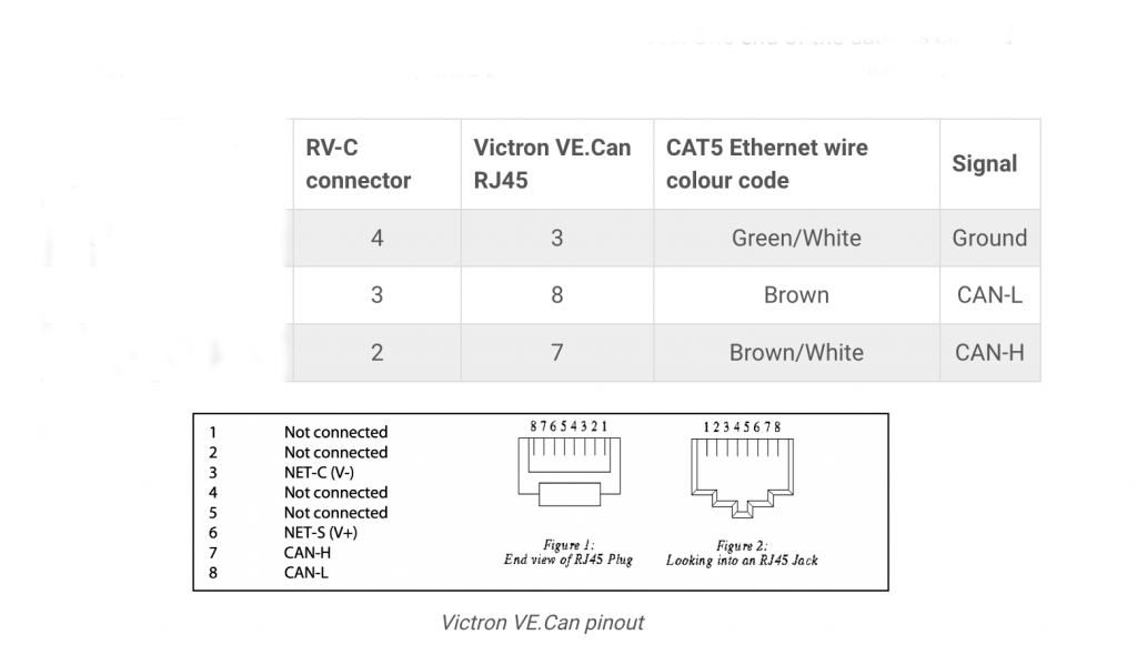

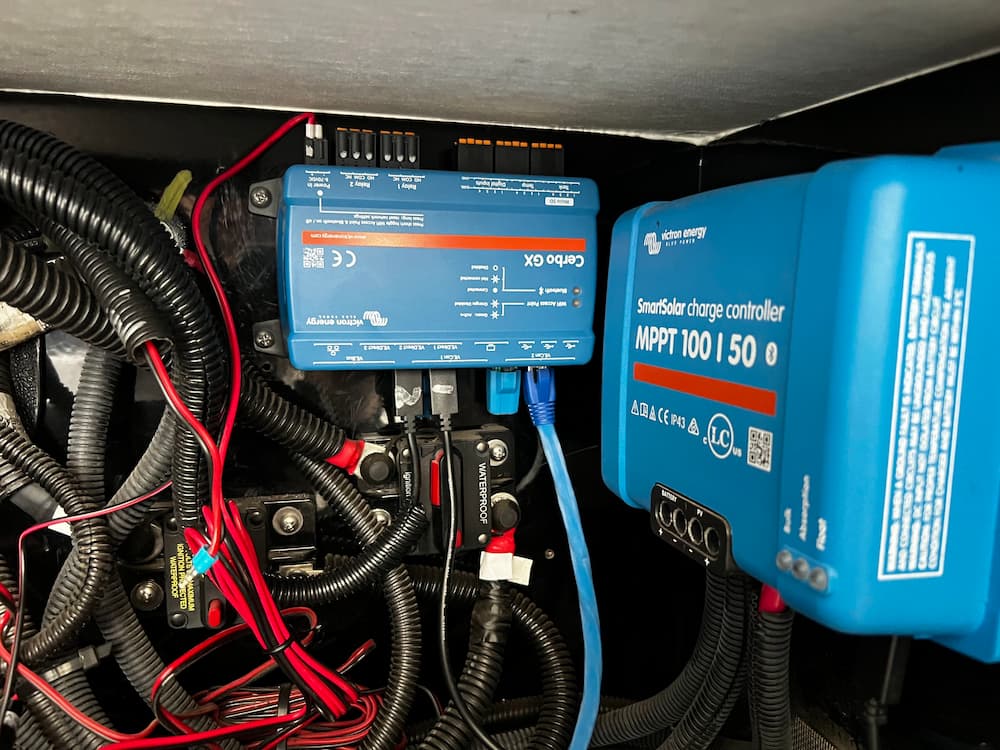
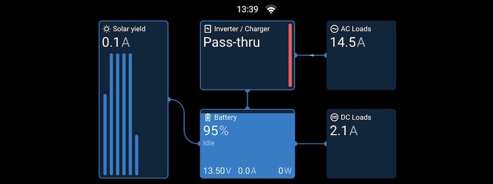

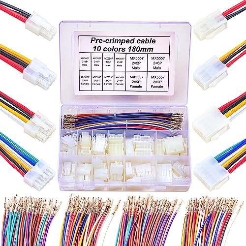

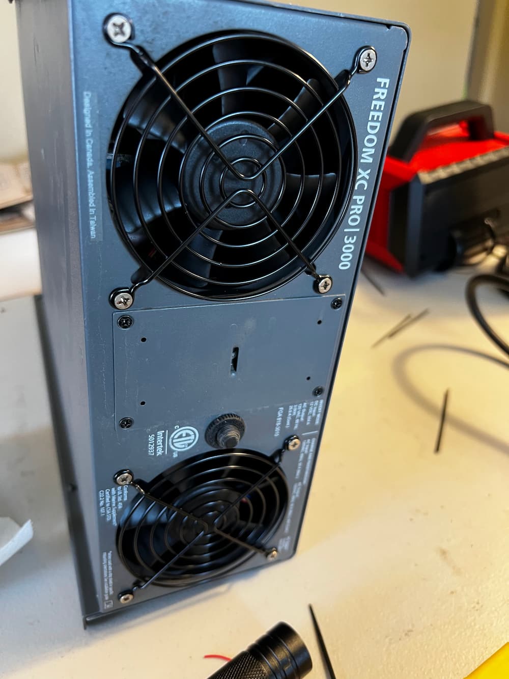
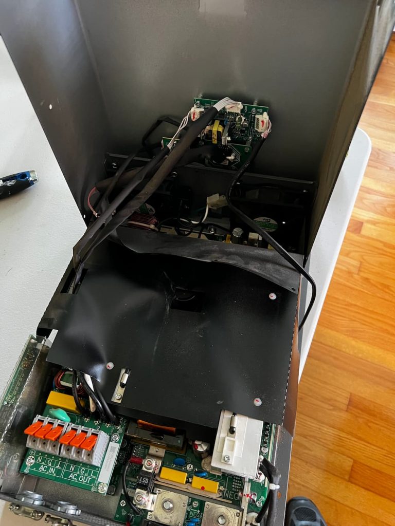
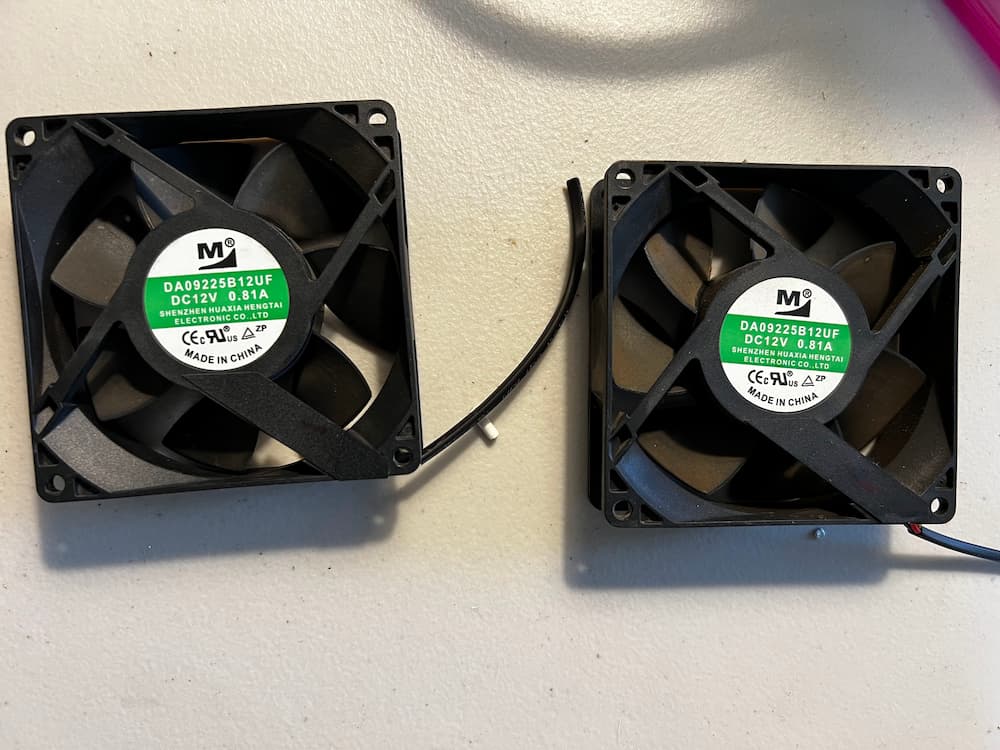

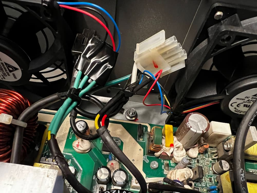

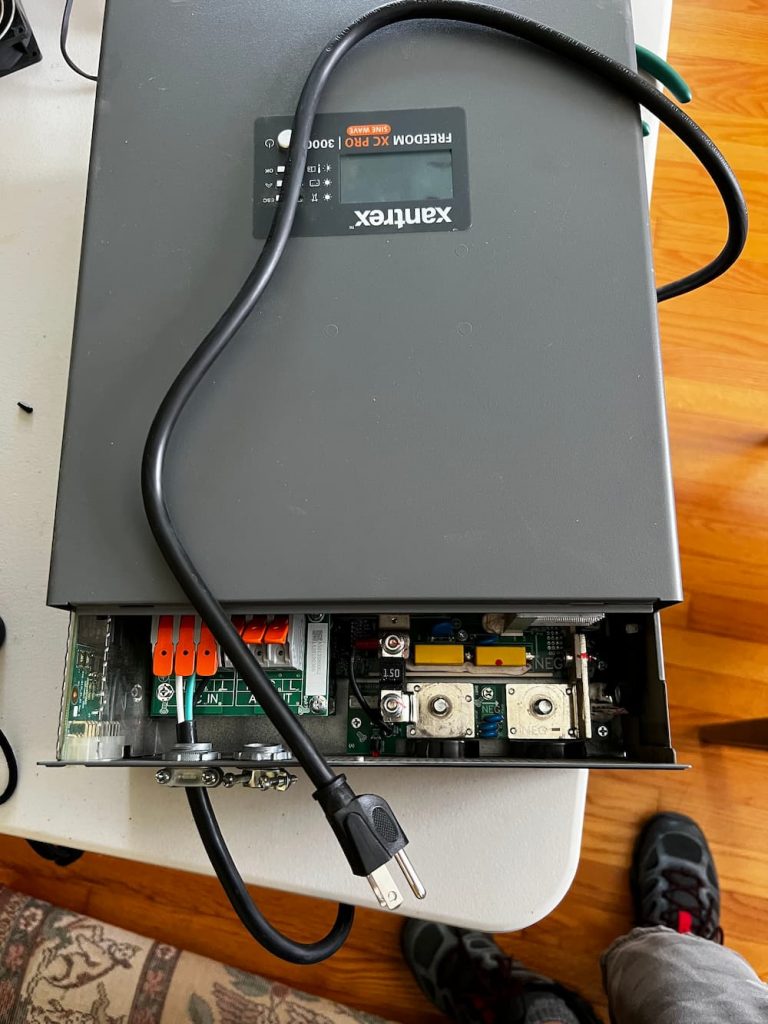
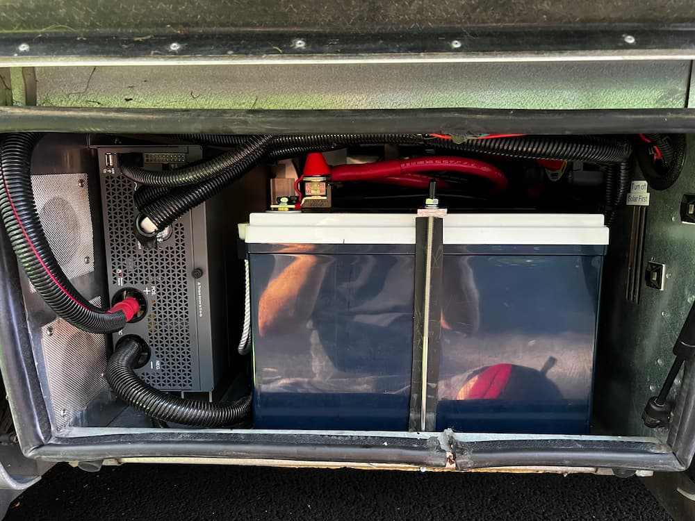


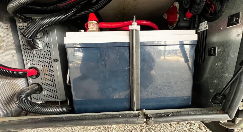
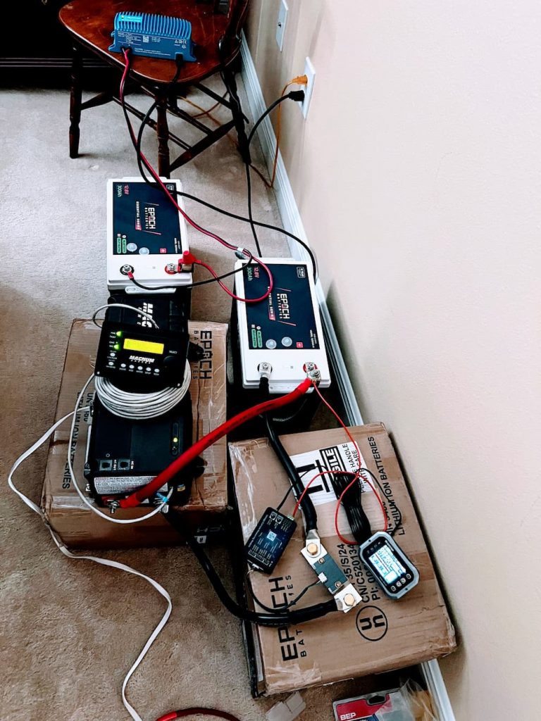
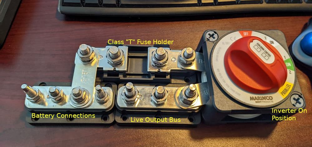
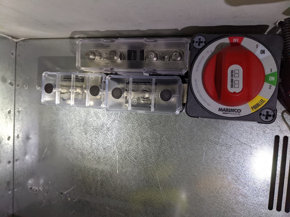
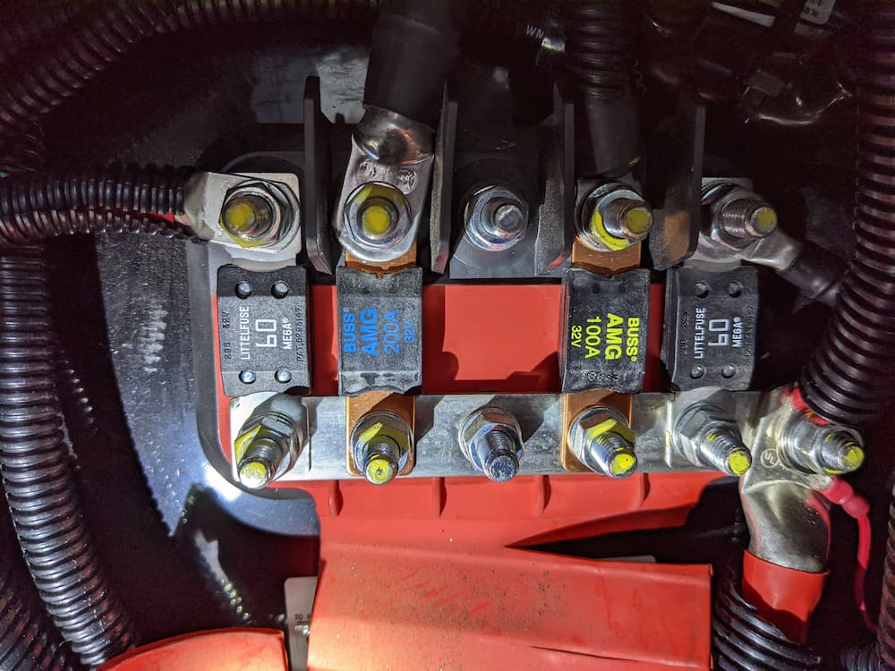


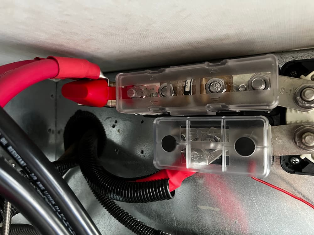
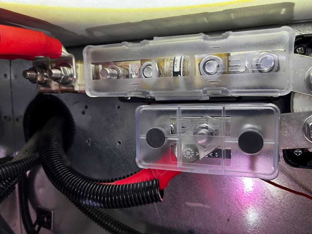


 MRBF Dual Fuse Bar